Download
1 / 50
500 likes | 603 Views
Discover cutting-edge space telescopes such as Hubble, Spitzer, Chandra, and JWST, providing unique views of the cosmos. Learn about their advanced instruments and capabilities revolutionizing our understanding of the universe.

E N D
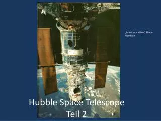
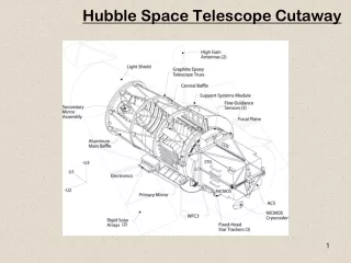
Hubble Space Telescope Field of View • WFC3 • ACS • STIS • COS • FGS
Spitzer Space Telescope • IRAC • IRS • MIPS
Chandra Space Telescope • ACIS • HRC • Spectral modes Advanced Charged Couple Imaging Spectrometer (ACIS): Ten CCD chips in 2 arrays provide imaging and spectroscopy; imaging resolution is 0.5 arcsec over the energy range 0.2 - 10 keV; sensitivity: 4x10-15 ergs/cm2/sec in 105 s High Resolution Camera (HRC): Uses large field-of-view mircro-channel plates to make X-ray images: ang. resolution < 0.5 arcsec over field-of-view 31x31 arc0min; time resolution: 16 micro-sec sensitivity: 4x10-15 ergs/cm2/sec in 105 s High Energy Transmission Grating (HETG): To be inserted into focused X-ray beam; provides spectral resolution of 60-1000 over energy range 0.4 - 10 keV Low Energy Transmission Grating (LETG): To be inserted into focused X-ray beam; provides spectral resolution of 40-2000 over the energy range 0.09 - 3 keV
Chandra Space Telescope: ACIS • Chandra Advanced CCD Imaging Spectrometer (ACIS)
Chandra Space Telescope: Spectroscopy • High Resolution Spectrometers - HETGS and LETGS • These are transmision gratings • low energy: 0.08 to 2 keV • high energy: 0.4 to 10 keV (high and medium resolution) • Groove spacings are a few hundred nm.
JWST • NIRCAM • NIRSPEC • MIRI
JWST: NIRCAM • Nyquist-sampled imaging at 2 and 4 microns -- short wavelength sampling is 0.0317"/pixel and long wavelength sampling is 0.0648"/pixel • 2.2'x4.4' FOV for one wavelength provided by two identical imaging modules, two wavelength regions are observable simultaneously via dichroic beam splitters.
JWST: NIRSPEC • 1-5 um; R=100, 1000, 3000 • 3.4x3.4 arcminute field • Uses a MEMS shutter for the slit
JWST: MIRI • 5-27 micron, imager and medium resolution spectrograph (MRS) • MIRI imager: broad and narrow-band imaging, phase-mask coronagraphy, Lyot coronagraphy, and prism low-resolution (R ~ 100) slit spectroscopy from 5 to 10 micron. • MIRI will use a single 1024 x 1024 pixels Si:As sensor chip assembly. The imager will be diffraction limited at 7 microns with a pixel scale of ~0.11 arcsec and a field of view of 79 x 113 arcsec. • MRS: simultaneous spectral and spatial data using four integral field units, implemented as four simultaneous fields of view, ranging from 3.7 x 3.7 arcsec to 7.7 x 7.7 arcsec with increasing wavelength, with pixel sizes ranging from 0.2 to 0.65 arcsec. The spectroscopy has a resolution of R~3000 over the 5-27 micron wavelength range. The spectrograph uses two 1024 x 1024 pixels Si:As sensor chip assemblies.
NIRSPEC/Keck Optical Layout Side View
NIRSPEC/Keck Optical Layout Top View
LSST Has a Big Focal Plane Wavefront Sensors (4 locations) Guide Sensors (8 locations) 3.5 degree Field of View (634 mm diameter)
History of Infrared Light Detection • Herschel’s detection of IR from Sun in 1800 • Johnson’s IR photometry of stars (PbS) mid 60’s • Neugebauer & Leighton: 2um Sky Survey (PbS), late 60’s • Development of bolometer (Low) late 60’s • Development of InSb (mainly military) early 70’s • IRAS 1983 • Arrays (InSb, HgCdTe, Si:As IBCs) mid-80’s • NICMOS, 2MASS, IRTF, UKIRT, KAO, common-user instruments, Gemini, etc. • JWST and the search for cosmic origins
Applications Imaging (single photon counting) Figures Courtesy of Don Hall (University of Hawaii)
Gamma Ray Detection Airshowers • It is possible to detect gamma rays by the presence of their by-products produced in Earth’s atmosphere. • Ground-based gamma ray telescopes actually detect Cherenkov radiation emitted by high energy particles produced through the interaction of the gamma rays and atmospheric particles.
Caltech Submillimeter Observatory (CSO) • CSO has a 10.4m primary dish. • SHARCII has 350, 450, 850um passbands, 12x32, 2.6x1amin field. • Dry nights lead to better sensitivity
Stratospheric Observatory for Infrared Astronomy (SOFIA) • SOFIA has 2.5m mirror. • It has a variety of instruments (see below) covering optical to FIR. • HAWK is being upgraded with new detectors and polarimeters.
Herschel • The Herschel telescope is a Cassegrain design with a 3.5m primary. The three scientific instruments are: • HIFI (Heterodyne Instrument for the Far Infrared), a very high resolution heterodyne spectrometer • PACS (Photodetector Array Camera and Spectrometer) - an imaging photometer and medium resolution grating spectrometer • SPIRE (Spectral and Photometric Imaging Receiver) - an imaging photometer and an imaging Fourier transform spectrometer • Covers 60-670 um.
Planck • The Planck telescope has an off-axis 1.5m primary. The scientific instruments are: • LFI (Low Frequency Instrument), a High Electron Mobility Transistor based radio receiver. • HFI (High Frequency Instrument), a bolometer based imaging array • Covers 300um to 1.2cm.
ALMA • The Atacama Large Millimeter/submillimeter Array • Covers 300um to a few cm
Radio Telescope Components • Reflector(s) • Feed horn(s) • Low-noise amplifier • Filter • Downconverter • IF Amplifier • Spectrometer
Antenna Fundamentals • An antenna is a device for converting electromagnetic radiation into electrical currents or vice-versa, depending on whether it is being used for receiving or for transmitting. • In radio astronomy, antennas are used for receiving. • The antenna receiver usually receives radiation from a dish, but it doesn’t have to. • For instance, the Long Wavelength Array (LWA) that has ~104 dipoles. At a wavelength of 15m, the dipoles have ~106 m2 of effective collecting area, where collecting area goes as wavelength squared, divided by 4 pi.
VLA Main Features • 27 radio antennas in a Y-shaped configuration • fifty miles west of Socorro, New Mexico • each antenna is 25 meters (82 feet) in diameter • data from the antennas are combined electronically to give the resolution of an antenna 36km (22 miles) across • sensitivity equal to that of a single dish 130 meters (422 feet) in diameter • four configurations: • A array, with a maximum antenna separation of 36 km; • B array -- 10 km; • C array -- 3.6 km; and • D array -- 1 km.
Very Long Baseline Array (VLBA) • ten radio telescope antennas • 25 meters (82 feet) in diameter and weighing 240 tons • Mauna Kea to St. Croix in the U.S. Virgin Islands • VLBA spans more than 5,000 miles, providing astronomers with the sharpest vision of any telescope on Earth or in space. • efforts to reduce funding • efforts to increase sensitivity (~6x)
Chandra Originally AXAF Advanced X-ray Astrophysics Facility http://chandra.nasa.gov/ Chandra in Earth orbit (artist’s conception)
Chandra Orbit • Deployed from Columbia, 23 July 1999 • Elliptical orbit • Apogee = 86,487 miles (139,188 km) • Perigee = 5,999 miles (9,655 km) • High above LEO Can’t be Serviced • Period is 63 h, 28 m, 43 s • Out of Earth’s Shadow for Long Periods • Longer Observations
Chandra Mirrors Assembled and Aligned by Kodak in Rochester “Rings”
Mirrors Integrated into spacecraft at TRW (NGST), Redondo Beach, CA(Note scale of telescope compared to workers)