Download
1 / 22
220 likes | 468 Views
Computational Analysis of Stall and Separation Control in Compressors. Lakshmi Sankar Saeid Niazi, Alexander Stein School of Aerospace Engineering Georgia Institute of Technology

E N D
Computational Analysis of Stall and Separation Control in Compressors Lakshmi Sankar Saeid Niazi, Alexander Stein School of Aerospace Engineering Georgia Institute of Technology Supported by the U.S. Army Research Office Under the Multidisciplinary University Research Initiative (MURI) on Intelligent Turbine Engines
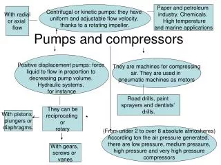
Motivation and Objectives • Use CFD to explore and understand compressor stall and surge • Develop and test flow control strategies (air-injection, bleeding) for compressors • Apply CFD to compare low-speed and high-speed configurations Compressor instabilities can cause fatigue and damage to entire engine
Summary of Earlier Accomplishments • 2-D rotating stall was numerically modeled, and the underlying physical phenomena studied • A 3-D flow solver capable of modeling unsteady viscous flow through axial and centrifugal compressors was developed and validated • The mechanisms behind the onset and growth of surge in NASA Low Speed Centrifugal Compressor was studied • Control of Surge through diffuser bleed was simulated
Bleed Valves Movable Plenum Walls Guide Vanes Air-Injection How to Control Surge (Passive Control) • Diffuser bleed valves • Pinsley, Greitzer, Epstein (MIT) • Prasad, Neumeier, Haddad (GT) • Movable plenum wall • Gysling, Greitzer, Epstein (MIT) • Guide vanes • Dussourd (Ingersoll-Rand Research Inc.) • Air-injection • Murray (Cal Tech) • Fleeter, Lawless (Purdue) • Weigl, Paduano, Bright (MIT & NASA Lewis)
Boundary Conditions (GTTURBO3D) Periodic Boundary at clearance gap Solid Wall Boundary at impeller blades Solid Wall Boundary at compressor casing Inflow Boundary Periodic Boundary at diffuser Solid Wall Boundary at compressor hub Outflow boundary (coupling with plenum) Periodic Boundary at compressor inlet
Plenum Chamber • u(x,y,z) = 0 • pp(x,y,z) = const. • isentropic . mt ap, Vp Outflow Boundary . mc Outflow BC (GTTURBO3D) Conservation of mass:
DLR High-Speed Centrifugal CompressorAGARD Test Case • 24 main blades • 30 backsweep • CFD-grid 141 x49 x 33 (230,000 grid-points) • Design Conditions: • 22360 RPM • Mass flow = 4.0 kg/s • Total pressure ratio = 4.7 • Adiab. efficiency = 83% • Exit tip speed = 468 m/s • Inlet Mrel = 0.92
Total Pressure Ratio DLRCC-Results (Off-Design Conditions)Performance Characteristic Map Unsteady fluctuations are denoted by size of circles Fluctuations at 3.1 kg/sec are 30 times larger than at 4.6 kg/sec
DLRCC-Results (Surge Conditions) Mild surge develops. Surge amplitude grows to 60% of mean flow rate. Surge frequency = 94 Hz (1/100 of blade passing frequency)
DLRCC-Results (Surge Conditions) Mild surge cycle colored by Mrel • Flow field vectors show two separation zones: • near leading edge • in the diffuser
DLRCC-Results (Surge Conditions)Stagnation pressure contours Direction of rotation • Vortex shedding causes reversed flow • Origin of separation occurs at leading edge pressure side
Casing 0.04RInlet 5° Impeller RInlet Rotation Axis LSCC-Results (Air-Injection) Injection angle, = 5º 3 to 10% injected mass flow rate
DLRCC-Results (Air-Injection)Different yaw angles, 3% injected mass flow rate Positive yaw angle is measured in positive direction of impeller rotation Yaw angle directly affects the unsteady leading edge vortex shedding
DLRCC-Results (Air-Injection) Velocity vectors colored by Mrel Leading edge separation suppressed due to injection
DLRCC-Results (Air-Injection)Different yaw angles, 3% injected mass flow rate
Axial Compressor (NASA Rotor 67) • 22 Full Blades • Inlet Tip Diameter 0.514 m • Exit Tip Diameter 0.485 m • Tip Clearance 0.61 mm • 22 Full Blades • Design Conditions: • Mass Flow Rate 33.25 kg/sec • Rotational Speed 16043 RPM • Rotor Tip Speed 429 m/sec • Inlet Tip Relative Mach Number 1.38 • Total Pressure Ratio 1.63 • Adiabatic Efficiency 0.93 Multi-flow-passage-grid for rotating stall modeling
Performance Map (NASA Rotor 67) • measured mass flow rate at choke: 34.96 kg/s • CFD choke mass flow rate: 34.76 kg/s
Mach Contours at Midspan Spatially uniform flow at design conditions
Summary of Current Year Work • The CFD compressor modeling capability was extended to: • Higher speed, higher pressure compression systems • Turbulence model • Shock capturing capability • Boundary conditions • Development of surge mechanism in centrifugal compressors was studied. Surge Control through upstream injection was optimized • In preparation for rotating stall simulations, a multi-blade passage version of the solver was developed and validated
Future and Planned Activities • 3-D rotating stall phenomenon and efficient stall control in axial compressors (bleeding, vortex generators) will be modeled • Develop a criterion for efficient injection control of centrifugal compressors • Examine the effectiveness of control laws developed by Drs. Haddad, Prasad and Neumeier through CFD-simulations
Technology Transition • The suite of codes may be used by industry partners for pilot studies of promising concepts: • Compact size of the code • Optimized for turbomachinery applications • Advanced analysis features (fifth order Roe solver, implicit time marching algorithm, Spalart-Allmaras model) • Documentation is available • Optimized injection control scheme may be implemented in real engines: • Injection location • Injection rates • Injection angles
Local Static Pressure, p/pstd DLRCC-Results (Design Conditions)Static Pressure Along Shroud Excellent agreement between CFD and experiment