Download
1 / 15
150 likes | 326 Views
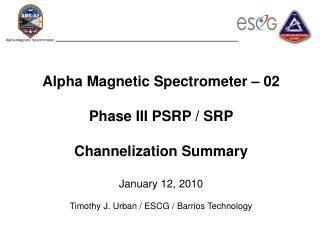
Alpha Magnetic Spectrometer – 02 Phase III PSRP / SRP Channelization Summary January 12, 2010 Timothy J. Urban / ESCG / Barrios Technology. AMS02 Channelization Summary Outline. AMS Heater Circuit Separation AMS TRD Gas Control Separation Cryo-Cooler Control Separation.

E N D
Alpha Magnetic Spectrometer – 02Phase III PSRP / SRPChannelization SummaryJanuary 12, 2010Timothy J. Urban / ESCG / Barrios Technology
AMS02 Channelization SummaryOutline • AMS Heater Circuit Separation • AMS TRD Gas Control Separation • Cryo-Cooler Control Separation Tim Urban / ESCG
AMS02 Channelization SummaryHeater Circuits • Typical heater circuitry does not route wires such that the controls (thermostats) are within wire bundles between the thermostat and the heater. • As an example, wake radiator examples are provided on the following pages. Tim Urban / ESCG
AMS02 Channelization SummaryWake Heater Circuits Tim Urban / ESCG
AMS02 Channelization SummaryWake Heater Circuits Tim Urban / ESCG
AMS02 Channelization SummaryWake Heater Circuits Tim Urban / ESCG
AMS02 Channelization SummaryWake Heater Circuit Separation Thermostats Heaters Tim Urban / ESCG
AMS02 Channelization SummaryWake Heater Circuit Separation Heaters Thermostats Tim Urban / ESCG
AMS02 Channelization SummaryTRD Gas System Circuits • TRD heater circuitry does not route wires such that the controls (thermostats) are within wire bundles between the thermostat and the heater. • Additional controls (i.e. valve control lines) are physically bundled in separate cable harnesses. Tim Urban / ESCG
AMS02 Electronics SummaryTRD Gas System TRD Gas 29VDC Heater Circuit Tim Urban / ESCG
AMS02 Electronics SummaryTRD Gas System TRD Gas 120VDC Heater Circuit Tim Urban / ESCG
AMS02 Electronics SummaryTRD Gas – Circuit Separation Tim Urban / ESCG
AMS02 Electronics SummaryTRD Gas – Circuit Separation Heater Control Lines Valve Control Lines Tim Urban / ESCG
AMS02 Channelization SummaryCCEB System Circuits CCEB utilizes independent means of controlling Cryocooler operation / maximum temperature: • J-Crate monitors GTSN temperature and removes PDS power (SSPC) to CCEB in over-temperature condition. • J-Crate monitors GTSN temperature and uses USCM control of CCEB to ramp-down Cryocooler power in over-temperature condition. • Internal and external Cryocooler sensors are monitored by independent sensors (in a physically separate cable harness – from above and eachother) and this data is used by separate subsystem in the CCEB to regulate power via PWM to Cryocooler Tim Urban / ESCG
AMS02 Electronics SummaryTRD Gas – Circuit Separation External Temperature Sensor PWM CC Power Line GTSN Temperature Sensor Tim Urban / ESCG

![AREA CONTROL SERVICE & SEPARATION [Air Traffic Control]](https://cdn4.slideserve.com/9172245/magesh-mani-bsacist-dt.jpg)