Download

1 / 17
220 likes | 787 Views
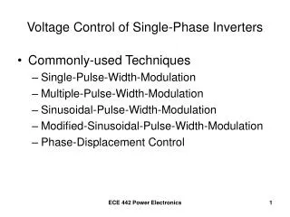
Voltage Control of Single-Phase Inverters. Commonly-used Techniques Single-Pulse-Width-Modulation Multiple-Pulse-Width-Modulation Sinusoidal-Pulse-Width-Modulation Modified-Sinusoidal-Pulse-Width-Modulation Phase-Displacement Control. Single-Pulse-Width-Modulation.

E N D
Voltage Control of Single-Phase Inverters • Commonly-used Techniques • Single-Pulse-Width-Modulation • Multiple-Pulse-Width-Modulation • Sinusoidal-Pulse-Width-Modulation • Modified-Sinusoidal-Pulse-Width-Modulation • Phase-Displacement Control ECE 442 Power Electronics
Single-Pulse-Width-Modulation ECE 442 Power Electronics
One Pulse per Half-Cycle Pulse Width Controls the Output Voltage ECE 442 Power Electronics
Carrier and Reference Signals Gate Pulse Gate Pulse • Compare the Reference Signal with the Carrier • Frequency of the Reference Signal determines the frequency of the Output Voltage • Modulation Index = M = Ar/Ac ECE 442 Power Electronics
Gate Signals and Output ECE 442 Power Electronics
rms value of the Output Voltage ECE 442 Power Electronics
Fourier Series for the Output Voltage ECE 442 Power Electronics
Times and angles of the intersections Pulse width d (or pulse angle δ) TS = T/2 ECE 442 Power Electronics
Harmonic Profile ECE 442 Power Electronics
Multiple-Pulse-Width-Modulation ECE 442 Power Electronics
Multiple Pulses per Half-Cycle of Output Voltage ECE 442 Power Electronics
Gate Signal Generation • Compare the Reference Signal with the Carrier • Frequency of the Reference Signal determines the Output Voltage Frequency • Frequency of the Carrier determines the number of pulses per half-cycle • Modulation Index controls the Output Voltage ECE 442 Power Electronics
Gate Signals and Output Voltage Number of pulses per half cycle = p = fc/2fo = mf /2 where mf = frequency modulation ratio ECE 442 Power Electronics
rms Value of the Output Voltage ECE 442 Power Electronics
Fourier Series of the Output Voltage ECE 442 Power Electronics
The times and angles of the intersections The pulse width d (or pulse angle δ) TS = T/2p ECE 442 Power Electronics
Harmonic Profile ECE 442 Power Electronics