Download
1 / 12
120 likes | 171 Views
Learn about the demands, role, and relevant physical processes for beam diagnostics in technical installations. Understand diverse beam quantities, diagnostics methods, and tools for accelerator commissioning and development.

E N D
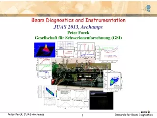
Beam Diagnostics and Instrumentation JUAS 2013, Archamps Peter Forck Gesellschaft für Schwerionenforschnung (GSI)
Demands on Beam Diagnostics Diagnostics is the ’organ of sense’ for the beam. It deals with real beams in real technical installations including all imperfections. • Four types of demands leads to different installations: • Quick, non-destructive measurements leading to a single number or simple plots. • Used as a check for online information. Reliable technologies have to be used. • Example: Current measurement by transformers. • Instruments for daily check, malfunction diagnosis and wanted parameter variation. • Example: Profile measurement, in many cases ‘intercepting’ i.e destructive to the beam • Complex instruments for severe malfunctions, accelerator commissioning & development. • The instrumentation might be destructive and complex. • Example: Emittance determination. • Instruments for automatic, active beam control. • Example: Closed orbit feedback using position measurement by BPMs. • A clear interpretation of the results is a important design criterion. • Non-destructive (’non-intercepting’) methods are preferred: • The beam is not influenced • The instrument is not destroyed.
The Role of Beam Diagnostics • The cost of diagnostics is about 3 to 10 % of the total facility cost: • 3 % for large accelerators or accelerators with standard technologies • 10 % for versatile accelerators or novel accelerators and technologies. Cost Examples: • The amount of man-power is about 10 to 20 %: • very different physics and technologies are applied • technologies have to be up-graded, e.g. data acquisition and analysis • accelerator improvement calls for new diagnostic concepts.
Relevant physical Processes for Beam Diagnostics • Electro-magnetic influence by moving charges: • → classical electro-dynamics,voltage and current meas., low and high frequencies • Examples: Faraday cups, beam transformers, pick-ups • Emission of photon by accelerated charges: (only for relativistic electrons) • → classical electro-dynamics, optical techniques (from visible to x-ray) • Example: Synchrotron radiation monitors • Interaction of particles with photons: • → optics, lasers, optical techniques, particle detectors • Examples: laser scanners, short bunch length measurement, polarimeters • Coulomb interaction of charged particles with matter: • → atomic and solid state physics, current measurement, optics, particle detectors • Examples: scintillators, viewing screens, ionization chambers, residual gas monitors • Nuclear- or elementary particle physics interactions: • → nuclear physics, particle detectors • Examples: beam loss monitors, polarimeters, luminosity monitors • And of cause accelerator physics for proper instrumentation layout. Beam diagnostics deals with the full spectrum of physics and technology, this calls for experts on all these fields and is a challenging task!
Beam Quantities and their Diagnostics I LINAC & transport lines: Single pass ↔Synchrotron: multi pass Electrons: always relativistic ↔ Protons/Ions: non-relativistic for Ekin < 1 GeV/u Depending on application: Low current ↔ high current Overview of the most commonly used systems:
Beam Quantities and their Diagnostics II • Destructive and non-destructive devices depending on the beam parameter. • Different techniques for the same quantity ↔ Same technique for the different quantities.
Typical Installation of a Diagnostics Device Modern trend: High performance ADC & digital signal processing → action of the beam to the detector → low noise pre-amplifier and first signal shaping accelerator tunnel: → analog treatment, partly combining other parameters → digitalization, data bus systems (GPIB, VME, cPCI...) local electronics room: → visualization and storage on PC → parameter setting of the beam and the instruments control room:
Example: Graphical User Interface for Beam Position Monitors The result helps to align the accelerator! Some experimental device parameters are also shown to prove the functionality.
Outline of the Lecture • The ordering of the subjects is oriented by the beam quantities: • Current measurement: Transformers, cups, particle detectors • Profile measurement: Various methods depending on the beam properties • Transverse emittance measurement: Destructive devices, determination by linear transformations • Pick-ups for bunched beams: Principle and realization of rf pick-ups, closed orbit and tune measurements • Measurement of longitudinal parameters: Beam energy with pick-ups, time structure of bunches for low and high beam energies, longitudinal emittance • Beam loss detection: Secondary particle detection for optimization and protection It will be discussed: The action of the beam to the detector, the design of the devices, generated raw data, partly analog electronics, results of the measurements. It will not be discussed: Detailed signal-to-noise calculations, analog electronics, digital electronics, data acquisition and analysis, online and offline software.... General: Standard methods and equipment for stable beams with moderate intensities.
Goal of the Lecture Signal generation Valid interpretation • The goal of the lecture should be: • Understanding the signal generation of various device • Showing examples for real beam behavior • Enabling a correct interpretation of various measurements.
Synchrotron, Bρ=18 Tm Emax p: 4.7 GeV U: 1 GeV/u Achieved e.g.: Ar18+: 1·1011 U28+: 3·1010 U73+: 1·1010 Ion Sources: all elements UNILAC SIS UNILAC FRS ESR ESR: Storage Ring, Bρ=10 Tm UNILAC: all ions p – U : 3 – 12 MeV/u, 50 Hz, max. 5 ms Up to 20 mA current Atomic & Plasma Physics Radiotherapy Nuclear Physics The Accelerator Facility at GSI