Download
1 / 30
340 likes | 788 Views
Chapter 31B - Transient Currents and Inductance. A PowerPoint Presentation by Paul E. Tippens, Professor of Physics Southern Polytechnic State University. © 2007. Objectives: After completing this module, you should be able to:.

E N D
Chapter 31B - Transient Currents and Inductance A PowerPoint Presentation by Paul E. Tippens, Professor of Physics Southern Polytechnic State University © 2007
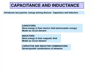
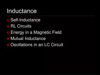
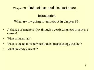
Objectives: After completing this module, you should be able to: • Define and calculate inductance in terms of a changing current. • Calculate the energy stored in an inductor and find the energy density. • Discuss and solve problems involving the rise and decay of current in capacitors and inductors.
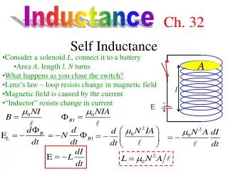
Increasing I Decreasing I R R Self-Inductance Consider a coil connected to resistance Rand voltage V. When switch is closed, the rising current I increases flux, producing an internal back emf in the coil. Open switch reverses emf. Lenz’s Law: The back emf (red arrow) must oppose change in flux:
Increasing Di/ Dt R Inductance The back emfE induced in a coil is proportional to the rate of change of the current DI/Dt. An inductance of one henry (H) means that current changing at the rate of one ampere per second will induce a back emf of one volt.
Di/ Dt = 2 A/s 4 mV R Example 1:A coil having 20 turns has an induced emf of 4 mV when the current is changing at the rate of 2 A/s. What is the inductance? L = 2.00 mH Note: We are following the practice of using lower case i for transient or changing current and upper case I for steady current.
Increasing Di/ Dt R Inductance L Calculating the Inductance Recall two ways of finding E: Setting these terms equal gives: Thus, the inductance L can be found from:
Solenoid l B and F = BA R Inductance L Inductance of a Solenoid The B-field created by a current I for length l is: Combining the last two equations gives:
l A R Example 2: A solenoid of area 0.002 m2 and length 30 cm, has 100 turns. If the current increases from 0 to 2 A in 0.1 s, what is the inductance of the solenoid? First we find the inductance of the solenoid: L = 8.38 x 10⁻⁵ H Note: L does NOT depend on current, but on physical parameters of the coil.
l A R Example 2 (Cont.): If the current in the 83.8-mH solenoid increased from 0 to 2 A in 0.1 s, what is the induced emf? L = 8.38 x 10⁻⁵ H
R Potential energy stored in inductor: Energy Stored in an Inductor At an instant when the current is changing at Di/Dt, we have: Since the power P= Work/t, Work = P Dt. Also the average value of Liis Li/2 during rise to the final current I. Thus, the total energy stored is:
L = 0.3 H R I = 2 A Example 3: What is the potential energy stored in a 0.3 H inductor if the current rises from 0 to a final value of 2 A? U = 0.600 J This energy is equal to the work done in reaching the final current I; it is returned when the current decreases to zero.
l A R Energy Density (Optional) The energy density u is the energy U per unit volume V Substitution gives u = U/V :
l A R Energy Density (Continued) Energy density: Recall formula for B-field:
l A R Example 4:The final steady current in a solenoid of 40 turns and length 20 cm is 5 A. What is the energy density? B = 1.26 mT Energy density is important for the study of electro-magnetic waves. u = 0.268 J/m3
V S1 S2 R L E The R-L Circuit An inductor L and resistor Rare connected in series and switch 1 is closed: i V – E = iR Initially, Di/Dt is large, making the back emf large and the current ismall. The current rises to its maximum value I when rate of change is zero.
i I 0.63 I Current Rise Time, t t The Rise of Current in L At t = 0, I = 0 At t = ¥, I = V/R The time constant t: In an inductor, the current will rise to 63% of its maximum value in one time constant t = L/R.
V S1 i S2 R E L The R-L Decay Now suppose we close S2after energy is in inductor: E = iR For current decay in L: Initially, Di/Dt is large and the emf Edriving the current is at its maximum value I. The current decays to zero when the emf plays out.
i I Current Decay 0.37 I Time, t t The Decay of Current in L At t = 0, i = V/R At t = ¥, i = 0 The time constant t: In an inductor, the current will decay to 37% of its maximum value in one time constant t.
16 V 5W R After time t: L = 0.04 H i = 0.63(V/R) Example 5: The circuit below has a 40-mH inductor connected to a 5-W resistor and a 16-V battery. What is the time constant and what is the current after one time constant? Time constant: t= 8 ms i = 2.02 A
E The R-C Circuit V Close S1. Then as charge Q builds on capacitor C, a back emf Eresults: S1 S2 i V – E = iR R C Initially, Q/C is small, making the back emf small and the current iis a maximum I. As the charge Q builds, the current decays to zero when Eb= V.
q Capacitor Qmax Increase in Charge Time, t 0.63 I t Rise of Charge t = 0, Q = 0, I = V/R t = ¥ , i = 0, Qm = C V In a capacitor, the charge Q will rise to 63% of its maximum value in one time constant t. The time constant t: Of course, as charge rises, the current iwill decay.
i Capacitor I Current Decay 0.37 I Time, t t The Decay of Current in C At t = 0, i = V/R At t = ¥, i = 0 The time constant t: As charge Q increases The current will decay to 37% of its maximum value in one time constant t; the charge rises.
V S1 S2 i R C E The R-C Discharge Now suppose we close S2and allow Cto discharge: E = iR For current decay in L: Initially, Q is large and the emf Edriving the current is at its maximum value I. The current decays to zero when the emf plays out.
Capacitor i I Current Decay 0.37 I t Time, t Current Decay At t = 0, I = V/R At t = ¥, I = 0 As the current decays, the charge also decays: In a discharging capacitor, both current and charge decay to 37% of their maximum values in one time constant t = RC.
12 V 3W R C = 4 mF After time t: i = 0.63(V/R) Example 6: The circuit below has a 4-mF capacitor connected to a 3-W resistor and a 12-V battery. The switch is opened. What is the current after one time constant t? t = RC = (3 W)(4 mF) Time constant: t= 12 ms i = 2.52 A
l A R Potential Energy Energy Density: Summary
Inductor i I Current Rise 0.63I t Time, t Summary In an inductor, the current will rise to 63% of its maximum value in one time constant t = L/R. The initial current is zero due to fast-changing current in coil. Eventually, induced emf becomes zero, resulting in the maximum current V/R.
i Inductor I Current Decay 0.37I t Time, t Summary (Cont.) The initial current, I = V/R, decays to zero as emf in coil dissipates. The current will decay to 37% of its maximum value in one time constant t = L/R.
q Capacitor Capacitor i Qmax I Increase in Charge Current Decay 0.37 I Time, t t Time, t 0.63 I t Summary (Cont.) When charging a capacitor the charge rises to 63% of its maximum while the current decreases to 37% of its maximum value.