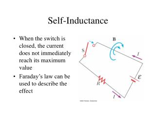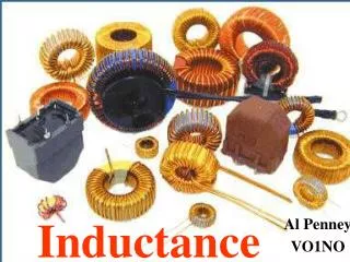
Inductance
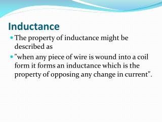
Inductance. The property of inductance might be described as "when any piece of wire is wound into a coil form it forms an inductance which is the property of opposing any change in current". Inductance. Alternatively it could be said

Inductance
E N D
Presentation Transcript
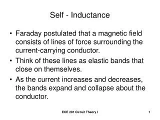
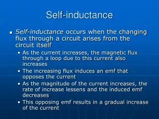
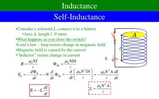
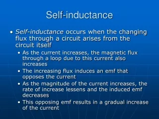
Inductance • The property of inductance might be described as • "when any piece of wire is wound into a coil form it forms an inductance which is the property of opposing any change in current".
Inductance • Alternatively it could be said • "inductance is the property of a circuit by which energy is stored in the form of an electromagnetic field".
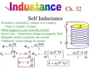
Inductance • We said a piece of wire wound into a coil form has the ability to produce a counter emf (opposing current flow) and therefore has a value of inductance.
Inductance • The standard value of inductance is the Henry, a large value which like the Farad for capacitance is rarely encountered in electronics today • Typical values of units encountered are milli-henries mH, one thousandth of a henry or the micro-henry uH, one millionth of a henry.
Inductance • A small straight piece of wire exhibits inductance (probably a fraction of a uH) although not of any major significance until we reach UHF frequencies. • The value of an inductance varies in proportion to the number of turns squared.
Inductance • If a coil was of one turn its value might be one unit. • Having two turns the value would be four units while three turns would produce nine units although the length of the coil also enters into the equation.
Inductance formula • The standard inductance formula for close approximation - imperial and metric is:
Imperial measurements • L = r2 X N2 / ( 9r + 10len ) where: L = inductance in uH r = coil radius in inches N = number of turns len = length of the coil in inches
Metric measurements • L = 0.394r2 X N2 / ( 9r + 10len ) where: L = inductance in uH r = coil radius in centimetres N = number of turns len = length of the coil in centimetres
Reactance • Reactance is the property of resisting or impeding the flow of ac current or ac voltage in inductors and capacitors. • Note particularly we speak of alternating current only ac, which expression includes audio af and radio frequencies rf.
Reactance • NOT direct current dc. • This leads to inductive reactance and capacitive reactance.
Inductive Reactance • When ac current flows through an inductance a back emf or voltage develops opposing any change in the initial current. • This opposition or impedance to a change in current flow is measured in terms of inductive reactance.
Inductive Reactance • Inductive reactance is determined by the formula: • 2 * pi * f * L • where: 2 * pi = 6.2832; f = frequency in hertz and L = inductance in Henries
Capacitive Reactance • When ac voltage flows through a capacitance an opposing change in the initial voltage occurs, • this opposition or impedance to a change in voltage is measured in terms of capacitive reactance.
Capacitive Reactance • Capacitive reactance is determined by the formula: • 1 / (2 * pi * f * C) • where: 2 * pi = 6.2832; f = frequency in hertz and C = capacitance in Farads
Some examples of Reactance • What reactance does a 6.8 uH inductor present at 7 Mhz? Using the formula above we get: • 2 * pi * f * L • where: 2 * pi = 6.2832; f = 7,000,000 Hz and L = .0000068 Henries • Answer: = 299 ohms
Some examples of Reactance • What reactance does a 33 pF capacitor present at 7 Mhz? Using the formula above we get: • 1 / (2 * pi * f * C) • where: 2 * pi = 6.2832; f = 7,000,000 Hz and C = .0000000000033 Farads • Answer: = 689 ohms
Resonance • Resonance occurs when the reactance of an inductor balances the reactance of a capacitor at some given frequency. • In such a resonant circuit where it is in series resonance, the current will be maximum and offering minimum impedance.
Resonance • In parallel resonant circuits the opposite is true. • Resonance formula • 2 * pi * f * L = 1 / (2 * pi * f * C) • where: 2 * pi = 6.2832; f = frequency in hertz L = inductance in Henries and C = capacitance in Farads
Resonance • Which leads us on to: • f = 1 / [2 * pi (sqrt LC)] • where: 2 * pi = 6.2832; f = frequency in hertz L = inductance in Henries and C = capacitance in Farads
Resonance • A particularly simpler formula for radio frequencies (make sure you learn it) is: • LC = 25330.3 / f 2 • where: f = frequency in Megahertz (Mhz) L = inductance in microhenries (uH) and C = capacitance in picofarads (pF)
Resonance • Following on from that by using simple algebra we can determine: • LC = 25330.3 / f 2 and L = 25330.3 / f 2 C and C = 25330.3 / f 2 L
Impedance at Resonance • In a series resonant circuit the impedance is at its lowest for the resonant frequency • whereas in a parallel resonant circuit the impedance is at its greatest for the resonant frequency. • See figure.
Impedance • Electrical impedance describes a measure of opposition to alternating current (AC). • Electrical impedance extends the concept of resistance to AC circuits,
Impedance • describing not only the relative amplitudes of the voltage and current, but also the relative phases. • When the circuit is driven with direct current (DC) there is no distinction between impedance and resistance; • the latter can be thought of as impedance with zero phase angle.
Impedance • The symbol for impedance is usually Z and it may be represented by writing its magnitude and phase in the form |Z|< θ
Combining impedances • The total impedance of many simple networks of components can be calculated using the rules for combining impedances in series and parallel.
Combining impedances • The rules are identical to those used for combining resistances, • except that the numbers in general will be complex numbers. • In the general case however, equivalent impedance transforms in addition to series and parallel will be required
Series combination • For components connected in series, the current through each circuit element is the same; • the total impedance is the sum of the component impedances
Parallel combination • For components connected in parallel, • the voltage across each circuit element is the same; • the ratio of currents through any two elements is the inverse ratio of their impedances
Parallel combination • Hence the inverse total impedance is the sum of the inverses of the component impedances
Diodes • Diodes are semiconductor devices which might be described as passing current in one direction only. • The latter part of that statement applies equally to vacuum tube diodes.
Diodes • Diodes can be used as voltage regulators, • tuning devices in rf tuned circuits, • frequency multiplying devices in rf circuits, • mixing devices in rf circuits, • switching applications or can be used to make logic decisions in digital circuits.
Diodes • There are also diodes which emit "light", of course these are known as light-emitting-diodes or LED's.
Types of Diodes • The first diode in figure is a semiconductor diode • Commonly used in switching applications • You will notice the straight bar end has the letter "k", this denotes the "cathode" while the "a" denotes anode.
Types of Diodes • Current can only flow from anode to cathode and not in the reverse direction, hence the "arrow" appearance. • This is one very important property of diodes
Types of Diodes • The second of the diodes is a zener diode which are fairly popular for the voltage regulation of low current powersupplies.
Types of Diodes • The next is a varactor or tuning diode. • Depicted here is actually two varactor diodes mounted back to back with the DC control voltage applied at the common junction of the cathodes. • These cathodes have the double bar appearance of capacitors to indicate a varactor diode.
Types of Diodes • When a DC control voltage is applied to the common junction of the cathodes, • the capacitance exhibited by the diodes (all diodes and transistors exhibit some degree of capacitance) will vary in accordance with the applied voltage.
Types of Diodes • The next diode is the simplest form of vacuum tube or valve. • It simply has the old cathode and anode. • These terms were passed on to modern solid state devices. • Vacuum tube diodes are mainly only of interest to restorers and tube enthusiasts
Types of Diodes • The last diode depicted is a light emitting diode or LED. • A led actually doesn't emit as much light as it first appears, • a single LED has a plastic lens installed over it and this concentrates the amount of light.
Types of Diodes • Seven LED's can be arranged in a bar fashion called a seven segment LED display and when decoded properly can display the numbers 0 - 9 as well as the letters A to F.