Download

1 / 27
390 likes | 921 Views
Explore the basic principles of capacitors and inductors, essential components in electrical circuits. A capacitor can store electric charge between two plates separated by an insulator, with capacitance measuring its ability to hold charge. Capacitors are described through formulas indicating their properties, such as capacitance (C = Q/V). Inductors, on the other hand, generate a magnetic field around a conductor when current flows through it. Understanding how these components work, including their voltage and charge relationships, is crucial for mastering electrical engineering concepts.

E N D
What is capacitor? • A device that can hold or store a reasonable amount of electric charge • It is made of two parallel plates separated by insulator( dielectric) or air • It has two leads that can be connected directly to other components • The ability to store amount of charges for a particular values of voltage is called capacity or capacitance and measured in Farad (F) . 1 Farad is defined as 1 Coulomb (C ) of electricity capacity at 1 V potential difference
Unit picofarads (pF) = 10-12 F nanofarads (nF) = 10-9 F microfarads (F) = 10-6 F millifarads (mF) = 10-3 F Farad (F) = 100 F
d d A Insulator (dielectric) Insulator (dielectric) Cross section fixed capacitor Polarized capacitor Variable capacitor Conductor dimensions and symbols
Plate A Plate B Capacitor R V Property of capacitor • Positive terminal of a battery repels the positive charges (positive ions) towards plate A and attracts negative charges (electrons) towards it – Plate A then becomes positive. • Negative terminal of a battery repels negative charges (electron) towards plate B and attracts positive charges (positive ion) towards it – Plate B then becomes negative charge. • Positive charges accumulate in plate A reduces more positive charges from the battery terminal to enter it and at the same time negative charges in also reduces more negative charges from the negative terminal of the battery.– the current flow from the battery the plate will be reduced.
Plate A Plate B Capacitor R V Property of capacitor • Charges develop the potential different between the plates and increase with the increase of charges. • When the potential different is same as the voltage of the battery, the entering of charges stop. • Charges are stored in the capacitor plates after the connection to the battery is disconnected. • Ratio of Q:V is constant and is called as capacitance, thus • C = Q/V or Q = CV
Capacitance Capacitance of a capacitor depends on its physical construction and given as: C = A/d [F] where = ro = absolute permittivity [F/m] r = relative permittivity [no unit] o = free space permittivity [8.854 x 10⁻¹² F/m] A = area of a plate [m2] d = distance between two plates [m]
Example 1 A capacitor made of two parallel plates of area 10 cm2 each. The plates are separated by an insulator of 0.5mm thickness and a relative permittivity equal to 5. Determine its capacitance. C = roA/d = (5 x 8.854 x 10-12 x 10 x 10-4)/0.5 x 10-3 = (5 x 8.854 x 10-12 x 10)/5 = 88.54 pF
Changing with time When the voltage applied to the capacitor changing with time , the charges also will change with time . Thus Q = CV becomes dq = C dv Then differentiate with time , we have therefore note integrates
Power in capacitor Power in capacitor is given by Energy for time dt is given by Total Energy Thus Energy stored in capacitor is
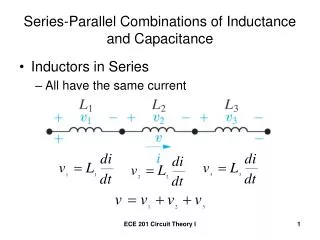
i(t) v1(t) C1 vT(t) v2(t) C2 Capacitors in series Using Kirchhoff‘s voltage law we have: vT(t) = v1(t) + v2(t) Both side have Same integration Note from previous slides Thus Generalized for n capacitors
i(t) v1(t) C1 vT(t) v2(t) C2 Distribution of voltage across capacitors in series Voltage across each capacitor (*) Taking the ratio But summation of voltage Then we have or Similarly Substitute in (*)
iT(t) i1(t) i2(t) v(t) C1 C2 Capacitors in parallel Using Kirchoff’s current law iT(t) = i1(t) + i2(t) CT = C1 + C2 To generalized for n capacitor , thus CT = C1 + C2 + ……. + Cn Note from previous slides
A B Example 2 Cs Total of series capacitors C2 and C3 The overall total
A B Example 3 Charges in the capacitors C1 and C2 are Q1 = 20 C and Q2 = 5 C respectively, determine the energy stored in C1, C2 and C3 and the total energy in all capacitors. C1 = 4.67 F; Q1 = 20 Q Therefore V1 = Q1/C1 = (20 x 10-6)/(4.67 x 10-6) = 4.3 V And W1 = ½C1(V1)2 = ½ x 4.67 x 10-6 x 4.32 = 43.2 J
continue C2 = 980 nF; Q2 = 5 Q Then V2 = Q2/C2 = (5 x 10⁻⁶)/(980 x 10-9) = 5.1 V W2 = ½C2(V2)2 = ½ x 980 x 10-9 x 5.12 = 12.7 J W3 = ½C3(V2)2 = ½ x 392 x 10-9 x 5.12 = 5.1 J
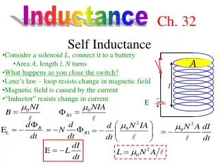
Inductance Electric current passing through a conductor will produce magnetic field or flux around it as shown in Figure.
If the wire conductor is wound around a core, magnetic filed /flux will resemble like permanent magnetic bar. • Magnitude of flux produced depends on magnitude of current ,I, properties of core , m,and physical construction (length , area of cross-section A and number of turn N)
Ohm’s law for flux where flux is equivalent to current I m.m.f. NI equivalent to e.m.f. V reluctance S equivalent to resistance R and is an absolute pemeability of core material and given by : = ro where o is a permeability of air (4 x 10⁻⁷ H/m) Substituting S in equation = NI/S: we have
Flux varies with time If the current in the inductor is varied with time (t), flux will also varied with time. Variation of flux in the windings will induce voltage. The induced voltage is: where: By introducing then Or for current
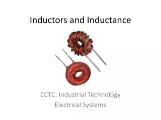
(b) –iron cored inductor (a) – air cored inductor (c) –ferrite-cored inductor (d) – variable inductor Units and symbols The inductance L is measured in Henry defined as a coil that induce 1 V when rate of current variation is 1 A/s. The units are: H = 10-6 H mH = 10-3 H H = 100 H Symbol for inductors:
Example 4 An inductor is built from a coil of 180 turns and the core is of iron having a relative permeability of 1500. The length of the core is 30 mm and area of cross section is 78.5 mm2. Calculate the value of the inductance. r = 1500; o = 4 x 10⁻⁷ H/m; A = 78.5 mm2; N = 180; l= 30 mm
Energy stored in inductor: Voltage Power For duration of dt sec For current changes between i = 0 to i = I Inductor stores energy in the form of magnetic fields.
i v1 vT v2 Inductors in series In general
iT i1 i2 Inductors in parallel In general
A 25 mH 60 mH 15 mH B Example 5 Effective inductance between A and B is: Le = L2 + L3 = 25 + 15 = 40 mH Lt = (L1 x Le)/(L1 + Le) = (60 x 40)/(60 + 40) = 24 mH
I = 600 mA A L2 150 mH 350 mH L1 L3 100 mH R1 R2 B Example 6 By supplying a total of constant current at 600 mA, L1 is found to store an energy of 28 mJ in its magnetic field. Calculate the total energy stored in all three inductors L1, L2 dan L3? W1 = ½L1I12 I1= ( 2W1/L1) = [(2 x 28 x 10-3)/(350 x 10-3)] = 400 mA I2 = I – I1 ( Kirchoff’s current law) = 600 – 400 = 200 mA Le= L2 + L3 = 150 + 100 = 250 mH We= ½LeI22= ½ x 250 x 10-3 x (200 x 10-3)2 = 5 mJ Total energy W = W1 + We = 28 + 5 = 33 mJ