Download
1 / 40
400 likes | 513 Views
This document covers the principles and implementation of multicast routing, a technique designed for efficient distribution of identical packet streams to selected workstations across multiple LANs. It discusses various multicast addressing schemes, the Internet Group Management Protocol (IGMP) for managing group memberships, and routing algorithms like PIM and DVMRP. The content highlights challenges such as network bandwidth utilization and routing loops, and explores options for shared and source-based multicast trees. Key insights into multicast address allocation and dynamic tree updates are also included.

E N D
Multicast Routing Wed. 28 MAY. 2003
Introduction based on number of receivers of the packet or massage: “A technique for the efficient distribution of identical packet streams to groups of selected workstations on one or more LANs.” (Penn State network and systems administrators)
Implementation • Multiple unicast Wast Network bandwidth, Registering mechanism. • Multiple addresses in a packet Can be only one instance(why Can?), Limited size of packet limits the max number of recipient Much more processing in a router(List of Addresses) Only partially help in the bandwidth wasting problem of the previous method • Multicast address The sender does not need to know the recipients, Must use connectionless UDP on top of IP
Implementation (Cont’s) • Saving the network link bandwidth is left to the routers, • the group does not have any physical or geographical boundaries. • Hosts that are interested in receiving data flowing to a particular group must join the group using IGMP.
Unicast/Multicast Unicast Host Router Multicast Host Router CISCO Systems
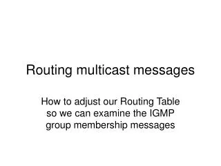
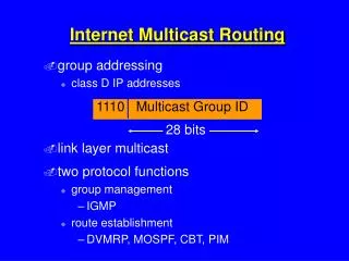
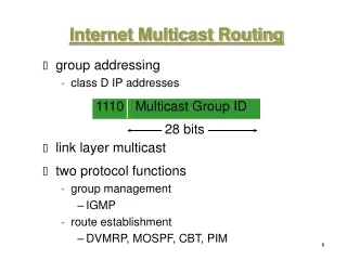
Internet Group Management Protocol • IGMP provides the means for a host to inform its attached router • Given that, the scope of IGMP interaction is limited to a host and its attached router • Another protocol is clearly required to coordinate the multicast- router throughout the internet, that accomplished by the network-layered multicast routing algorithms such as PIM, DVMRPand MOSPT. • Router queries the local hosts for m-cast group membership info • Hosts respond with membership reports: actually, the first host which responds, speaks for all
IGMP protocol • IGMPv1, there are just two different type of IGMP message: Membership QUERYand Membership REPORT When there is no reply to three consecutive IGMP membership queries, the router times out group an stops forwarding traffic directed toward group. • IGMPv2, there are four types.basically the same as version 1. the main difference: 1) The hosts communicate to the local multicast router when intention to leave the group. 2) The router then sends out a group-specific query and determines whether there are any remaining host.
IP Multicast Addresses • Multicast addresses specify an arbitrary group of IP hosts that have joined the group and want to receive traffic sent to this group. • The Internet Assigned Numbers Authority (IANA) controls theassignment of IP multicast addresses. • all IP multicast group addresses will fall in the range of224.0.0.0 to 239.255.255.255.(IPv4 D-classful) 224.0.0.0 - 244.0.0.255 link local scope 224.0.1.0 - 238.255.255.255 global scope 239.0.0.0 - 239.255.255.255Reserved for local scope 239.192.0.0 - 239.194.255.255 organization local scope 239.253.0.0 - 239.255.255.255 site local scope
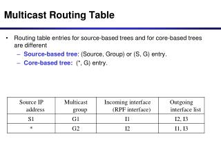
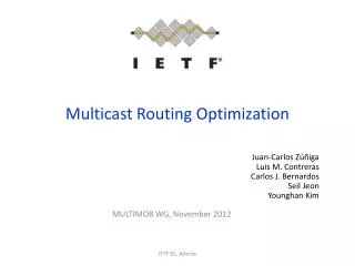
Routing protocol Multicast • Problem: find the best (e.g., min cost) tree which interconnects all the members
Multicast Tree Option • GROUP SHARED TREE: single tree for all senders(entire multicast group); bidirectional links • SOURCE BASED TREE:each source is the root of its own tree connecting to all members; thus separate trees for different senders
Group Shared Tree • Uses a single common root placed at some chosen point in the network (rendezvous point). • Source must send their traffic to the root, and then the traffic is forwarded down the shared tree to reach all receivers. • Message are replicated only where the tree branch • Member can any time join or leave, so the distribution trees must be dynamically update.(Prune,graft) • finding a minimum cost tree is known as the Steiner tree problem(NP-complete) • Alternate: Center-based approach - under some circumstances,the paths might not be the optimal paths - Network designers must carefully consider the placement of the RP when implementing an environment with only shared trees.
Source-based Tree • Source is the root of the multicast tree and whose branches form a spanning tree through the network to the receivers. • Also known as Short Path Tree(SPT) because tree uses the shortest path through the network. • SPT creating the optimal path between the source and receivers. This guarantees the minimum amount of network latency. • Routers must maintain the state of each link (link-state) • A simpler multicasting routing algorithm,need much less link state information, is the Reverse Path Forwarding(RPF).
Reverse Path forwarding • RPF makes use of the existing unicast routing table • A router forwards a multicast packet only if it is received on the up stream interface.
Multicast Routing Algorithms and Protocols • Flooding a router thatreceives a packet with multicast destination address, simply sends to all interfaces, expect the interface where the packet came to the router. Challenge:Routing Loops News: uses a article path history OSPF: uses link state database Using a list of last seen packets would need a lot of memory in current high speed routers and the checking if the packet is inthe list would slow down therouter. IP TTL is usually the best way to take care of this problem.
TTL local host……………. 0 local network segment.. 1 site…………………… 15 region………………… 31 country………………..48 continent(Europe)……. 63 world ………………... 127
Multicast Routing Alg.s and Prot.s (Cont’s) • Spanning tree Building a logical network on top of the real network by creating a loopless graph between all nodes resolves the looping problem in flooding . bandwidth wasterbutrobust and simple to implement • Reverse-path forwarding,RPF The basic idea is to generate an implicit spanning tree for each source in the network starting from the source to other nodes. using shortest paths gives the fastest possible delivery, not concentrate the traffic on some network links. Do not really use the group membership information, so waste bandwidth.
Multicast Routing Alg.s and Prot.s (Cont’s) • RPF and Prunes When the first packet in a multicast transmission reaches the end leaves in the routing tree, the leaf router sends a pruning message upstream if it does not have any group members attached to it. Likewise, if a any router in the tree receives a prune message from all of its downstream interfaces it sends a prune message upstream. The purpose of the prune message is to prevent sending unneeded following packets in that group to the pruned branch. There is still a one bad point the first packet in a group is always flooded in the whole network.
Multicast Routing Alg.s and Prot.s (Cont’s) • Steiner trees The idea of steiner trees is to build an overlay network that connects all nodes in a group with minimum total number of links It is not usually suitable in real networks The computing of the tree is hard and it must be done again each time a node joins or leaves a group. • Core-based trees Each multicast group has a core, The traffic of one group concentrates on certain links. There is not that first flood message in a group
Routing protocol Multicast • Intra domain - MOSPF - DVMRP (Flood & Prune) - PIM - Sparse mode - Dense mode • Inter domain - MBGP + MSDP Currently used - BGMP + MASC
Protocol Independent Multicast(PIM) Why independent? Independent of the underlying unicast routing protocol EIGRP, OSPF, BGP, or static routes. • Dense mode many or most of routers in the area need to be involved in routing multicast datagram. • Sparse mode the number of routers with attached group members is small with respect to total number of routers.
Link Data Control A B G C D F H E I Dense Mode PIM Example Source Receiver 1 Receiver 2
A B G C D F H E I Dense Mode PIM Example Source Initial Flood of Dataand Creation of State Receiver 1 Receiver 2
A B G C D F H E I Dense Mode PIM Example Source Prune to Non-RPF Neighbor Prune Receiver 1 Receiver 2
A B G C D F H E I Dense Mode PIM Example Source C and D Assert to DetermineForwarder for the LAN, C Wins Asserts Receiver 1 Receiver 2
A B G C D F H E I Dense Mode PIM Example Source I Gets Pruned E’s Prune is Ignored G’s Prune is Overridden Prune Join Override Prune Receiver 1 Receiver 2
A B G C D F H E I Dense Mode PIM Example Source New Receiver, I Sends Graft Graft Receiver 1 Receiver 2 Receiver 3
A B G C D F H E I Dense Mode PIM Example Source Receiver 1 Receiver 2 Receiver 3
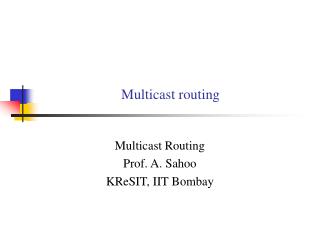
Link Data Control Sparse Mode PIM Example Source A B D RP C E Receiver 1 Receiver 2
Sparse Mode PIM Example Receiver 1 Joins Group GC Creates (*, G) State, Sends(*, G) Join to the RP Source A B D RP Join C E Receiver 1 Receiver 2
Sparse Mode PIM Example RP Creates (*, G) State Source A B D RP C E Receiver 1 Receiver 2
Sparse Mode PIM Example Source Sends DataA Sender Registers to the RP Source Register A B D RP C E Receiver 1 Receiver 2
Sparse Mode PIM Example RP de-encapsulates RegistersForwards Data Down the Shared TreeSends Joins Towards the Source Source Join Join A B D RP C E Receiver 1 Receiver 2
Sparse Mode PIM Example RP Sends Register-Stop OnceData Arrives Natively Source Register-Stop A B D RP C E Receiver 1 Receiver 2
Sparse Mode PIM Example C Sends (S, G) Joins to Join theShortest Path (SPT) Tree Source A B D RP (S, G) Join C E Receiver 1 Receiver 2
Sparse Mode PIM Example When C Receives Data Natively,It Sends Prunes Up the RP tree forthe Source. RP Deletes (S, G) OIF andSends Prune Towards the Source Source (S, G) Prune A B D RP (S, G) RP Bit Prune C E Receiver 1 Receiver 2
Sparse Mode PIM Example New Receiver 2 JoinsE Creates State and Sends (*, G) Join Source A B D RP (*, G) Join C E Receiver 1 Receiver 2
Sparse Mode PIM Example C Adds Link Towards E to the OIFList of Both (*, G) and (S, G)Data from Source Arrives at E Source A B D RP C E Receiver 1 Receiver 2
Sparse Mode PIM Example New Source Starts SendingD Sends Registers, RP Sends JoinsRP Forwards Data to Receiversthrough Shared Tree Source Register Source 2 A B D RP C E Receiver 1 Receiver 2
Hope be useful Thanks Hassan Salmani