Download
1 / 62
620 likes | 735 Views
Learn about multicast routing protocols, differences between dense and sparse modes, PIM-SM, RPF, MRIB, PIM-SM phases, DRs, RPs, and RPT to SPT switch. Explore XORP tool for process visualization.

E N D
Multicast Routing Babu Ram Dawadi
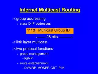
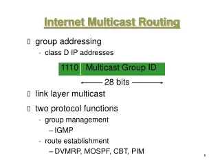
Index • What is a multicast routing protocol? • What are the differences between dense mode and sparse mode protocols? • What is PIM-SM? • What is RPF (Reverse Path Forwarding)? • What is MRIB? • Explain the three phases of PIM-SM. GWE. • Explain the roles of Designated Routers. • Explain the roles of Rendezvous Points. • Explain how a RPT to SPT switch is triggered. • Learn how to see the above processes using XORP. GWE.
Multicast Routing Protocol • Multicast communications is define as one-to-many or many-to-many communications • In multicasting, the router may forward the received packets through several of its interfaces. • In this case, router may copy the data when it is necessary, and forward it to the receivers. The router may forward received packets through several interfaces Fig. 1. Multicast Routing
Multicast Routing Protocol (cont) • Multicast routing protocol doesn’t support reliable transport layer protocol such as TCP • Source does not care about how many downstream receivers are receiving the data • It is impossible to maintain the reliable TCP connections with all of the receivers. UDP is commonly used for multicast traffic. If a packet is missed by receiver, the packet will simply lost and will not be retransmitted Fig. 2. Multicast Routing Protocol Stack
Multicast Routing Protocol • Multicast Routing Protocol consists of: • DVMRP (Distance Vector Multicast Routing Protocol) • PIM-DM (Protocol Independent Multicast - Dense Mode) • CBT (Core Based Tree) • PIM-SM (Protocol Independent Multicast – Sparse Mode) • and others……. • They each serve a different purpose. Routing Sparse Mode Dense Mode PIM PIM-SM CBT DVMRP PIM-DM Fig. 2. Types of Unicast Routing Protocol
Dense Mode Multicast Routing Protocol • DVMRP and PIM-DM are the 2 examples of multicast routing protocol in this category. • As the name implies, Dense Mode is optimized for densely populated communities of receivers. • Using Source based tree (S,G) • Routers simply floods multicast traffic streams to all interfaces. (FLOOD) • If downstream routers have no receiver require this particular multicast stream, it will send “stop” message to upstream router. (PRUNE)
Source Multicast Packets Receiver Dense Mode – Flood and Prune Routers simply floods multicast traffic streams to all interfaces (S, G) State created in everyrouter in the network!
Multicast Packets Prune Messages Dense Mode – Flood and Prune Downstream routers have no receiver, so send a prune messages to prune unwanted traffic. Source Receiver
Multicast Packets Dense Mode – Flood and Prune Finally, after pruning, only downstream with receiver will receive the traffic. But the Flood and prune process will repeat every 3 minutes Source Receiver
Sparse Mode Multicast Routing Protocol • PIM-SM or CBT • Routers must specifically request a particular multicast stream before the data is forwarded to them. • PIM SM implements forwarding trees for each multicast group • creating routing tree for a group with Rendezvous Point (RP) as a root for the tree • Rendezvous Point Tree (RPT) • Explicit join model • Receivers send Join towards the RP • Sender send Register towards the RP • Support both Source Based Tree (S,G) and Shared Based Tree (*,G)
Reverse Path Forwarding (RPF) • RPF is used to verify that a router receives a multicast packet on the correct incoming interface. • RPF algorithm • makes use of the existing unicast routing table to determine the upstream and downstream neighbors • Using unicast routing information • to create a distribution tree along the reverse path from the receivers towards the source • RPF check helps to guarantee that the distribution tree will be loop-free
eth2 eth0 Receiver 2 Router 3 eth1 eth0 eth2 eth1 Router 1 eth1 Source FF02::101/16 eth0 eth2 Router 2 Receiver 1 Reverse Path Forwarding (RPF)
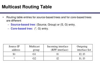
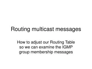
MRIB - Multicast Routing Information Base • Multicast Routing Information Base • Multicast topology table • Derived from the unicast routing table or from other routing protocols • Unicast routing table • OSPF • PIM-DM uses the MRIB to make decisions regarding RPF interfaces. • PIM know where to send (*,G) and (S,G) Join/Prune messages
Three phases of PIM-SM • 3 phases of PIM – SM to build a multicast distribution tree • RP Tree • Register Stop • Shortest Path Tree
Rendezvous Points Tree (RPT) • In shared tree • Root of the distribution tree is a router, not a host • In PIM-SM multicast routing protocol • the core router at the root of the shared tree is the rendezvous point (RP ) • The traffic from upstream and join/prune message from downstream routers “rendezvous” at this core router. • To join the Shared Tree (host want to receive multicast traffic) • Router or DR executes an RPF check on the RP address in its routing table • Produces the interface closest to the RP. • Send a join message (*,G) out on this interface. • These upstream routers • Repeat the those 3 processes until it reaches the RP. • It is building the shared tree or RPT as it goes until it reaches the RP.
Register Stop • Sources of multicast traffic don't necessarily join the group to which they are sending data • First Hop Router (FHR) or DR can receive the traffic without knowing the information on how to send the traffic to the RP through the tree. • It encapsulates the packet and send to RP as unicast packet.(Register Msg) • RP de-encapsulates theRegister message and forwards the extracted data packet to downstream members on the RPT • Encapsulation at DR and decapsulation for Register message at RP is not efficient • RP initiates a (S,G) Join toward S and the path to source is established. • DR starts sending traffic from S using both native multicast and Register-encapsulated messages • RP detected a duplicated multicast packets, it will send a “Register Stop” message to tell DR stop sending Register Message. • DR stop sending the Register message and RP now only receive the packet from native multicast packet.
Shortest Path Tree (SPT) • RP is a place for a source and receivers to meet • But if there is too many multicast group “rendezvous” there, it might become a bottleneck • Hence, establishing SPT might solve this problem and also reduce the path delay from Source to receives • SPT can be accomplish by specifying an SPT-Threshold in terms of bandwidth. • If this threshold is exceeded, the last-hop DR joins the SPT • To build the SPT • Router executes an RPF check on the source address in its routing table to find the interface closest to the source. • Issues an (S,G) Join to the RPF next router toward S.
Shortest Path Tree (SPT) (cont) • Each upstream router repeats this process, until • Arrives at the subnet of S • Router that already has (S,G) Join state. • The DR at the Source subnet then starts forwarding packets onto the source tree to the receiver • Now, the receiver's DR, it receives packets from Shared Tree (RP) and Source Tree (SPT). To stop receiving duplicating traffics, • Receiver's DR sends a PIM Prune message towards the RP router. • This message is known as (S,G,rpt) Prune, to tell RP this particular traffic coming in from the RPT are no longer needed • PIM Prune message is received by the RP router, then it stops sending this particular multicast traffic down to the receiver's DR.
Receiver 1 Designated Routers (DR) • The DR is a router which directly-connected to receivers and sources. • Sets up multicast route entries • Sends corresponding Join/Prune and Register messages on behalf of receivers and sources. • The sender with the largest IP address assumes the role of DR RP DR Router A Router B 10.207.160.1 10.207.160.2 If multiple routers exist on a single segment, “designated router” will be elected 10.207.160.0/24 10.207.160.100
Roles of Rendezvous Points • The RP is the root of particular group shared tree • RP-Tree. • The distribution center of PIM-SM • Multicast the traffic from the source to the downstream routers that have receivers • Responsible for forwarding information from the source to all registered receivers.
RP Source R1 Receiver 1 PIM-SM – Joining the Shared Tree RP created the (*,G) state (*,G) was created only along the shared tree Receiver 1 Joins Group G, and Router (R1) creates (*,G) state and send the (*, G) Join message to its upstream PIM neighbor, in the direction to the RP First Hop Router (FHR) Last Hop Router (LHR) IGMP or MLD, Receiver listen to Group, G
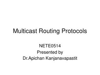
RP Source R1 (S,G) Register message - - - - unicast Multicast Traffic Flow (S,G) Join Message Source Tree Multicast Traffic Flow Receiver 1 PIM-SM – Registering with the RP The multicast data from the source (including headers) is encapsulated in the register message so that the RP can forward the data while adding the source to the tree RP de-encapsulates each Register message and forwards the extracted data packet to downstream members on the RPT RP add FHR into the RPT Sources of multicast traffic can always send the traffic. They no need to Join to any group FHR will send a “register” message to the RP. The register message is a unicast message addressed directly to the RP RP detects the normal multicast packets, it sends a Register-Stop message to FHR, ask FHR to stop sending register packets. RP sends PIM “join” to FHR. First Hop Router (FHR) Once the shortest path is established, from the source to the RP, the FHR begins sending traffic to the RP as standard IP multicast packets as well as encapsulated within Register messages. RP will temporary receive some packets twice. Legend Last Hop Router (LHR) Shared tree
RP Source R1 Source Tree Multicast Traffic Flow Receiver 1 PIM-SM – Registering with the RP Source traffic flows nativelyalong SPT to RP. First Hop Router (FHR) The multicast traffic flown down from RP to Receiver through Shared Tree Legend Last Hop Router (LHR) Shared tree
RP Source R1 (S, G) Prune Message Source Tree Multicast Traffic Flow Receiver 1 PIM-SM – Shortest Path Tree (switching) (S, G) traffic flow is no longer needed by the RP so it Prunes the flow of (S, G) traffic. (S, G) Traffic flow is now pruned off of the Shared Tree and is flowing to the Receiver via the Source Tree. When a downstream router detects there is an available shorter path, it can send a PIM-SM “join” message directly to the FHR. First Hop Router (FHR) The LHR now receives two copies of the multicast traffic packets - source node - Rendezvous Point (RP). Traffic begins flowing down the new branch of the Source Tree Additional (S, G) State is created along new part of the Source Tree (S, G) Traffic flow is now only flowing to the Receiver via a single branch of the Source Tree and Receiver is receiving traffic using SPT Legend Additional (S, G) State is created along the Shared Tree to prune off (S, G) traffic. Last Hop Router (LHR) Shared tree
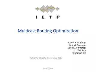
Sparse Mode Dense Mode Summary: Dense mode vs Sparse mode diagram
XORP Introduction • Extensible Open Router Platform • Multicast routing protocols for IPv4 and IPv6 • XORP is free • The XORP core developer team • International Computer Science Institute in Berkeley, California
XORP-Installation • XORP can be divided into two subsystems: • kernel-space • user-space • kernel-space • handles the forwarding path and provides API to the userspace • MROUTING kernel option must be activated • PIM kernel option must be activated in order to run PIM-SM • User-space • Default Configuration file: /usr/local/xorp/config.boot • Requirements : GNU make and Net-SNMP
XORP-Configuration • Explicitly enables the two rl0 and rl1 physical interfaces for XORP operation. • default-system-config • Tell FEA that the interface is configured using the existing interface information from the underlying system. interfaces { interface rl0 { description: "upstream interface" disable: false default-system-config } interface rl1 { description: "downstream interface" disable: false default-system-config } }
XORP-Configuration (cont) mfea6 (Multicast Forwarding Engine Abstraction) -must be configured if the XORP router is to be used for IPv6 multicast routing. vif ( virtual interface) -To enable or disable vif to be used for multicast IPv6 forwarding. In this example, we are not using it. interface register_vif -Enable it for PIM-SM operation, it is for PIM-SM register messages and must enable in mfea is PIM-SM is configured. plumbing { mfea6 { disable: false interface rl0 { vif rl0 { disable:false } } interface rl1 { vif rl1 { disable false } } interface register_vif { vif register_vif { disable: false } } } }
XORP-Configuration (cont) protocols { mld { disable: false interface rl0 { vif rl0 { disable: false } } interface rl1 { vif rl1 { disable: false } } } MLD (Multicast Listener Discovery) -MLD is configured if the XORP router is to be used for multicast routing - Track multicast group membership for directly connected subnets.
XORP-Configuration (cont) pimsm6 -If the XORP router is used for multicast routing for the PIM-SM domain, the PIM-SM should be configured. dr-priority - This command is used for setting the priority for the XORP router. If this command is not stated in the configuration, default priority value =1 will be used. -This parameter is used for the Designated Router election. pimsm6 { disable: false interface rl0 { vif rl0 { disable: false } } interface rl1 { vif rl1 { disable: false } } interface register_vif { vif register_vif { disable: false } }
bootstrap -Mechanism for elect RP dynamically. cand-bsr -Configured the XORP routers as candidate Bootstrap Routers (BSR) Scope-zone -A router intended to be a Candidate-BSR it must advertise for each zone (scope-zone & non-scope-zone) bsr--priority -Router with the highest priority value will be elected as BSR. Hash-mask-len -Unknown, leave it as default cand-rp -XORP router is to be a Candidate-RP, group-prefix - Candidate-RP it must advertise for each zone rp-priority - Router with highest priority will be elected as RP XORP-Configuration (cont) bootstrap { disable: false cand-bsr { scope-zone ff00::/32 { cand-bsr-by-vif-name: "rl1" bsr-priority: 128 hash-mask-len: 30 } } cand-rp { group-prefix ff00::/32 { cand-rp-by-vif-name: "rl1" rp-priority: 192 rp-holdtime: 150 } } }
XORP-Configuration (cont) switch-to-spt-threshold { /*approximately 1K bytes/s (10Kbps) threshold */ disable: false interval: 100 bytes: 102400 } } Switch-to0spt-threshold -used to specify the multicast data bandwidth threshold. -Used for Shortest Path Tree (SPT) switching interval: 100 bytes: 102400 -if total 10240 bytes arrive within 100 seconds, switch to SPT
XORP-Configuration (cont) fib2mrib { disable: false } } • fib2mrib • If the unicast routing protocol is not configured in and inject routes into MRIB, this parameter will be used. • It will get the Forwarding Information Base (FIB) from the system and pass it to the MRIB.
XORP – Case Study (Topology) 2001:d30:101:EF::/64 Source rtadvd Router-51 em1 ::1:1 2001:d30:1EF:1::/64 em0 ::1:3 em0 ::1:2 Router-52 Router-53 em1 ::2:2 2001:d30:1EF:3::/64 em0 ::3:6 em0 ::2:5 RP Router-55 Router-56 rtadvd em1 ::5:5 em1 ::4:6 2001:d30:1EF:5::/64 2001:d30:1EF:4::/64 Receiver
Router-51 Initial State – No Queries A B To show bootstrap info only To show interfaces status D C To show RP info only To show Bootstrap and RP info Router 51 knows where is the RP located, it is at Router 2001:d30:1ef:5::5:5 Router 51 knows where is the BSR located, it is at Router 2001:d30:1ef:5::5:5
Router-52 Initial State – No Queries (cont) A B To show interfaces status To show bootstrap info only C D To show Bootstrap and RP info To show RP info only Router 52 knows where is the RP located, it is at Router 2001:d30:1ef:5::5:5 Router 52 knows where is the BSR located, it is at Router 2001:d30:1ef:5::5:5
Router-53 Initial State – No Queries (cont) A B To show interfaces status To show bootstrap info only D C To show Bootstrap and RP info To show RP info only Router 53 knows where is the RP located, it is at Router 2001:d30:1ef:5::5:5 Router 53 knows where is the BSR located, it is at Router 2001:d30:1ef:5::5:5
RP BSR Router-55 Initial State – No Queries (cont) A B To show interfaces status To show bootstrap info only D C To show Bootstrap and RP info To show RP info only Router 55 is configured as a BSR and RP statically, in the diagram B and C , there is an additional information about BSR and RP in Router 55.
Router-56 Initial State – No Queries (cont) A B To show interfaces status To show bootstrap info only D C To show Bootstrap and RP info To show RP info only Router 56 knows where is the RP located, it is at Router 2001:d30:1ef:5::5:5 Router 56 knows where is the BSR located, it is at Router 2001:d30:1ef:5::5:5
Router-51 Router-55 Router-54 Router-53 Router-52 Initial State – No Queries (cont) All show pim6 join return an empty result because there is no request from the receiver
Initial State – No Queries em0 NOT DR Source VIF Router-51 em1 NOT DR em0 NOT DR em0 DR Summary for the DR election on this topology Router-53 Router-52 em1 NOT DR em1 DR em0 em0 NOT DR DR RP Router-55 Router-56 BSR DR em1 DR em1 Receiver
Case Study : XORP Configuration & Observation Phase 1 Building RP Tree Phase 2 Register Start/Stop
Receiver wishes to receive - Request 2001:d30:101:EF:20c:29ff:fe9f:f3af 2001:d30:101:EF::/64 Source Router-51 em1 ::1:1 2001:d30:1EF:1::/64 em0 ::1:3 em0 ::1:2 Now, the receiver intended to receive a traffic, Thus, receiver make a request to Router-56 (*,G) (*,G) Router-52 Router-53 em1 ::2:2 2001:d30:1EF:3::/64 (*,G) em0 ::3:6 (*,G) em0 ::2:5 RP Router-55 Router-56 Request em1 ::5:5 em1 ::4:6 2001:d30:1EF:5::/64 2001:d30:1EF:4::/64 Receiver
Request Receiver wishes to receive - Request Receiver An example of the screen shot on using SSMPINGD at receiver
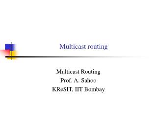
Router-51 Building RP Tree Route-51 is directly connected to the source through em0, and RP is connected at direction of em1 Now there is a receiver request for the traffic. In show pim6 join, it shows that Router-51 is directly connected to the source. Router-51 is connected to (S,G) through vif In the upstream, there is no RP forwarder. But Router-51 knows where is the RP for this particular group. It sends the Register message to RP. The status now is the FHR had joined to the RP (Router-55)
RP is connected towards at interface em1 Router-52 WC = Wild Card (*,G) If Router 52 found that there is no more specific match for particular source , the packet will be forwarded according to the next hop entry. DR is at em0. DR at em0 join the multicast wildcard entry for the group Current status for Router-52 is joined to the multicast group Building RP Tree (cont)