Download
1 / 20
210 likes | 570 Views
Three Other Types of Counters (BCD Counter, Ring Counter, Johnson Counter). Hun Wie (Theo) SJSU, 2011 Spring Prof: Dr. Sin-Min Lee CS147 Computer Organization and Architecture. Counters

E N D
Three Other Types of Counters (BCD Counter, Ring Counter, Johnson Counter) Hun Wie (Theo) SJSU, 2011 Spring Prof: Dr. Sin-Min Lee CS147 Computer Organization and Architecture
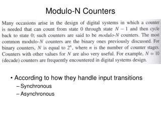
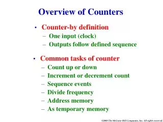
Counters • In digital logic and computing, a counter is a device which stores (and sometimes displays) the number of times a particular event or process has occurred, often in relationship to a clock signal.
Counters(Continued) • We examine special types of addition and subtraction operations, which are used for the purpose of counting. • We will show how the counter circuits can be designed using D flip-flops.
Electronic counters • In electronics, counters can be implemented quite easily using register-type circuits such as the flip-flop, and a wide variety of classifications exist: 1. Asynchronous (ripple) counter – changing state bits are used as clocks to subsequent state flip-flops 2. Synchronous counter – all state bits change under control of a single clock 3. Decade counter – counts through ten states per stage
Electronic counters(continued) 4. Up/down counter – counts both up and down, under command of a control input 5. Ring counter – formed by a shift register with feedback connection in a ring 6. Johnson counter – a twisted ring counter 7. Cascaded counter
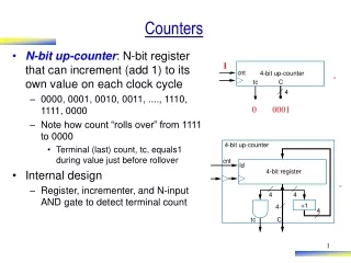
D0 = Q0 XOR Enable • D1 = Q1 XOR Q0 & Enable • D2 = Q2 XOR Q1 & Q0 & Enable • D3 = Q3 XOR Q2 & Q1 & Q0 & Enable
2x1 MUX to select input, loading external when to clear, loading internal value when to count.
BCD • In computing and electronic systems, binary-coded decimal (BCD) (sometimes called natural binary-coded decimal, NBCD) or, in its most common modern implementation, packed decimal, is an encoding for decimal numbers in which each digit is represented by its own binary sequence. Its main virtue is that it allows easy conversion to decimal digits for printing or display, and allows faster decimal calculations. Its drawbacks are a small increase in the complexity of circuits needed to implement mathematical operations. Uncompressed BCD is also a relatively inefficient encoding—it occupies more space than a purely binary representation. • In BCD, a digit is usually represented by four bits which, in general, represent the decimal digits 0 through 9. Other bit combinations are sometimes used for a sign or for other indications (e.g., error or overflow). • Although uncompressed BCD is not as widely used as it once was, decimal fixed-point and floating-point are still important and continue to be used in financial, commercial, and industrial computing.
Basics for BCD • To encode a decimal number using the common BCD encoding, each decimal digit is stored in a 4-bit nibble: • Decimal: 0 1 2 3 4 5 6 7 8 9 • Thus, the BCD encoding for the number 127 would be: 0001 0010 0111 • Whereas the pure binary number would be: 0111 1111 BCD: 0000 0001 0010 0011 0100 0101 0110 0111 1000 1001
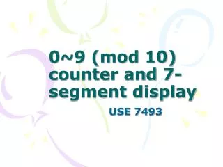
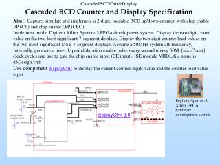
Consists of two modulo-10 counters, one for each BCD digit. • It is necessary to reset the four flip-flops after the count of 9 has been obtained. Thus the Load input to each stage is equal to 1 when Q3=Q0=1, which causes 0s to be loaded into the flip-flops at the next positive edge of the clock signal. • Keeping the Enable signal for BCD1 low at all times except when BCD0 = 9
IBM and BCD • IBM used the terms binary-coded decimal and BCD for 6-bit alphamerics codes that represented numbers, upper-case letters and special characters. Some variation of BCD alphamerics was used in most early IBM computers, including the IBM 1620, IBM 1400 series, and non-Decimal Architecture members of the IBM 700/7000 series. • Today, BCD data is still heavily used in IBM processors and databases, such as IBM DB2, mainframes, and Power6. In these products, the BCD is usually zoned BCD (as in EBCDIC or ASCII), Packed BCD (two decimal digits per byte), or "pure" BCD encoding (one decimal digit stored as BCD in the low four bits of each byte). All of these are used within hardware registers and processing units, and in software.
Ring Counter Ring counters are implemented using shift registers. It is essentially a circulating shift register connected so that the last flip-flop shifts its value into the first flip-flop. There is usually only a single 1 circulating in the register, as long as clock pulses are applied. (Starts 1000->0100->0010->0001 repeat)
Start control signal, which presets the left-most flip-flop to 1 and clears the others to 0.
Johnson Counter The Johnson counter, also known as the twisted-ring counter, is exactly the same as the ring counter except that the inverted output of the last flip-flop is connected to the input of the first flip-flop. Let’s say, starts from 000, 100, 110, 111, 011 and 001, and the sequence is repeated so long as there is input pulse.
Truth Table for a 4-bit Johnson Ring Counter As well as counting or rotating data around a continuous loop, ring counters can also be used to detect or recognize various patterns or number values within a set of data. By connecting simple logic gates such as the AND or the OR gates to the outputs of the flip-flops the circuit can be made to detect a set number or value. Standard 2, 3 or 4-stage Johnson ring counters can also be used to divide the frequency of the clock signal by varying their feedback connections and divide-by-3 or divide-by-5 outputs are also available.
To initialize the operation of the Johnson counter, it is necessary to reset all flip-flops, as shown in the figure. Observe that neither the Johnson nor the ring counter will generate the desired counting sequence if not initialized properly.
Sources : • Digital Logic ,Stephen Brown • http://www.doc.ic.ac.uk/~nd/surprise_96/journal/vol4/cwl3/report.html#bcd • http://people.wallawalla.edu/~curt.nelson/engr354/lecture/brown/chapter7_reg_counters.pdf • http://www.electronics-tutorials.ws
Questions? Thank you !