X-Ray Computed Tomography Inspection
X-Ray Computed Tomography Inspection of the Stardust Heat Shield IPPW7 June 14 – 18, 2010 Barcelona, Spain.

X-Ray Computed Tomography Inspection
E N D
Presentation Transcript
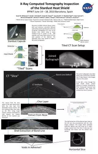
X-Ray Computed Tomography Inspection of the Stardust Heat Shield IPPW7 June 14 – 18, 2010 Barcelona, Spain Karen M. McNamara(1), Daniel J. Schneberk(2), Daniel M. Empey(3)*, Ajay Koshti(1), D. Elizabeth Pugel(4), Ioana Cozmuta(5), Mairead Stackpoole(5), Norman P. Ruffino(6), Eddie C. Pompa(6), Ovidio Oliveras(6) and Dean A. Kontinos(7) (1)NASA Johnson Space Center, (2)Lawrence Livermore National Labs, (3)Sierra Lobo, Inc., (4)NASA Goddard Space Flight Center, (5)Eloret Corporation, (6)Jacobs Technology, (7)NASA Ames Research Center Heat Shield X-ray Source Detector Side View Personnel at NASA Johnson Space Center (JSC) and Lawrence Livermore National Labs (LLNL) recently performed a full X-ray Computed Tomography (CT) scan of the Stardust heat shield using a newly installed X-ray CT system at JSC. 900 separate scans were taken (every 0.4°) for each position of the detector. The individual scans were joined to make a 900 joined radiographs. Top View Object Rotation(about center) Stardust Capsule Tiled CT Scan Setup Detector Heat Shield Joined Radiograph “Tiled” Scans The joined radiographs described above were processed to provide the CT data shown in the images shown on this poster. To the left, a slice through the heat shield shows several features of interest including the PICA, honeycomb structure and the bond-line. Also visible are artifacts from the CT process. Bond-Line Defect? CT “Slice” CT Artifacts Char Layer This extract from the nose region of the heat shield shows both the char layer that developed during reentry and the individual fibers that make up the PICA. Using image analysis software developed by LLNL (Ingrec) the relative density of the material was measured. Extract from Nose The shell extraction of the adhesive layer show to the left was also accomplished with the LLNL Imgrec software. This image shows potential bond-line defects that also show up in other images created from from the CT data (see the horizontal slice below and the vertical slice above). Shell Extraction of Bond-Line Voids in Adhesive? Horizontal Slice