Download
1 / 1
10 likes | 98 Views
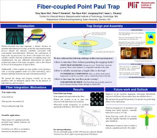
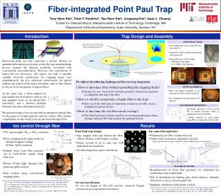
Designing a novel ion trap with integrated optical fiber for unified ion control. Study covers trap construction, alignment methods, and preliminary ion-fiber overlap results. Future outlook includes ion positioning optimization and quantum simulation. Utilizes fiber for qubit light delivery and ion manipulation.

E N D
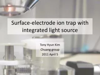
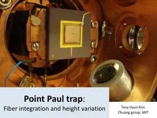
Fiber-integrated Point Paul Trap Tony Hyun Kim1, Peter F. Herskind1, Tae-Hyun Kim2, Jungsang Kim2, Isaac L. Chuang1 1Center for Ultracold Atoms, Massachusetts Institute of Technology, Cambridge, MA 2Department of Electrical Engineering, Duke University, Durham, NC Introduction Trap Design and Assembly We address the following challenges in fiber-ion trap integration: How to introduce fiber without perturbing the trapping fields? How to reliably incorporate a fragile fiber to the trap? How to fine-tune the ion-fiber mode overlap? POINT PAUL TRAP Mode field diameter of the qubit light (674nm) at ion height of 1mm is 72um, giving an alignment tolerance of 4°. • Ion confinement with a single RF ring electrode.[5] • Gaps due to fiber modeled numerically and analytically. • Typical RF drive 300V, 8MHz • 200meV trap depth • ~0.5MHz trap frequency Surface-electrode ion traps represent a distinct advance in quantum information processing, in that the trap manufacturing process assumes the inherent scalability associated with conventional microfabrication. However, the construction of large-scale ion processors will require not only a sensibly scalable electrode architecture for trapping many ions simultaneously, but also additional infrastructure for optical readout and control of the many ion qubits, such as that offered by device-level integration of optical fibers. We present design of an ion trap with an integrated optical fiber for the purpose of light delivery and ion control. This scheme complements recent work[3] on ion detection through fibers. GND RF Fiber introduced through the center of innermost electrode (actually an optical ferrule). Single-mode fiber for both qubit (674nm) and Doppler cooling (422nm) transitions of 88Sr+. GND 12mm OPTICAL FERRULE • Fiber and ferrule polished as in conventional fiber connectorization. • Axis alignment with precision of 25 microns. Design of a new “Point Paul” electrode geometry whose axial symmetry is compatible with that of the fiber. At the same time, a fiber-coupled ion trap enables novel structures such as ion trap quantum nodes on an optical fiber network[1], and a interface platform between ions and cold neutral atoms[2]. 1.25mm Rely on off-the-shelf optical components as much as possible, such as standardized optical ferrules. ION MICROPOSITIONING • Ion height adjusted in situ by second RF on ferrule electrode. Order of magnitude variation feasible. • ~100um variation in radial plane using RF on compensation electrodes. The Point Paul trap is ideally suited for an ion micropositioning scheme through additional RFs that translate the quadrupole node. Ion control through fiber Results • 88Sr+ optical qubit: 5S1/2↔4D5/2 transition • Fiber simultaneously single-mode for: • 422nm: Doppler cooling • 674nm: Qubit transition • Ion control through fiber: • Preliminary ion-fiber overlap observed. • Further improvement in alignment expected. • Point Paul trap design: • Ions trapped with and without the fiber. >Hours lifetime with Doppler cooling. • Planar crystals of up to nine ions with individual ion resolution. • Secular frequencies agree with theory. Ion shelving due to qubit laser. (Data shows free-space 674nm delivery; similar observations made with fiber 674.) (Prototype fiber/ferrule trap used different fab procedure than one outlined above.) Preliminary qubit spectroscopy through the fiber: Numerous sidebands indicate insufficient ion cooling • Doppler beam from fiber prepares ion in Lamb-Dicke regime along fiber axis. • Pulsed 674nm light through fiber performs qubit rotation. • State readout using conventional imaging optics. (Each panel: 70um´70um) DC electrodes RF1 Free-space beam delivery FUTURE OUTLOOK • Reoptimization of Point Paul geometry for additional ion positioning in the radial plane. • Test of anomalous ion heating near metal surfaces, currently believed to scale as 1/(ion height)4.[6] • Quantum simulation using planar crystals. Fiber RF2 Oven 40K chamber (5” diameter) of cryostat. [4] Trap mount is at 4K • Ion micropositioning: • In situ ion height of 200-1100 microns achieved. Height variation in good agreement with theory. [1] J. I. Cirac, P. Zoller, H. J. Kimble, and H. Mabuchi. Phys. Rev. Lett., 78, 3221 (1997) [2] C.A. Christensen, S. Will, M. Saba, G.-B. Jo, et al. Phys. Rev. A78 , 033429 (2008) [3] A. P. VanDevender, Y. Colombe, J. Amini, D. Leibfried and D.J. Wineland. Phys. Rev. Lett., 105, 023001 (2010) [4] P.B. Antohi, D. Schuster, G.M. Akselrod, et al. Rev. Sci. Instrum., 80, 013103 (2009). [5] C. Pearson. Theory and Application of Planar Ion Traps. S.M. thesis, MIT (2006) [6] L. Deslauriers, S. Olmschenk, D. Stick, et al. Phys. Rev. Lett.,97, 103007 (2006).