Download
1 / 18
180 likes | 205 Views
Outline of muon system, chamber design, threshold setting, and cosmic particle flux testing presented at IEEE NSS 2008. Chamber technology, electronics, requirements, and performance discussed in detail.

E N D
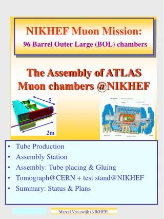
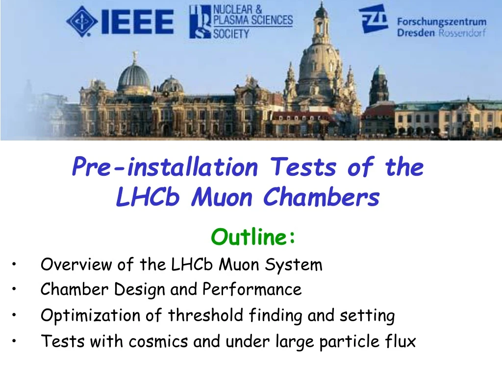
Pre-installation Tests of the LHCb Muon Chambers Outline: • Overview of the LHCb Muon System • Chamber Design and Performance • Optimization of threshold finding and setting • Tests with cosmics and under large particle flux Burkhard Schmidt, CERNOn behalf of the LHCb Muon Group IEEE NSS 2008, Dresden
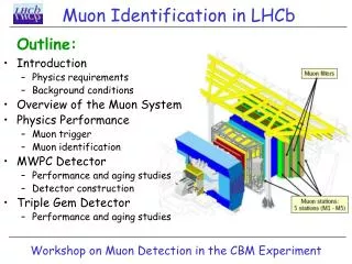
The LHCb Muon Detector Purpose: • Identification of muons • Triggering on muons produced in the decay of b-hadrons by measuring PT M1 M2 M3 M4 M5 • 5 Muon stations, one in front • and 4 behind the calorimeters • 435m2 of detector area • with 1380 chambers • Hadron Absorber of 20 • thickness in total Main Requirement: -> A muon trigger requires the coincidence of hits in all 5 stations within a bunch crossing (25ns) in a region of interest that selects the muon PT IEEE NSS 2008, Dresden
Muon Detector Layout • Space point measurement • 4 Regions with granularity • variable with distance from • beam axis • - 0.6cm x 3.1cm in Region 1, • 5cm x 25cm in Region4 • Particle flux varies between • - 0.5 MHz/cm2 (M1 Region 1) • - 0.2 kHz/cm2 (M5 Region 4) Chamber Detector Technology :-MWPC will be used in most regions - triple GEMs are used in station M1 R1 Electronics: - System has 126k FE-channels, reduced to 26k readout channels IEEE NSS 2008, Dresden
MWPC Readout Types Region 4: Anode wire readout Region 3: Cathode pad readout Region 1+2: (in stations M2+M3) Combined anode and cathode readout -> Different readouts and variations in input capacitance pose special requirements on FE-chip IEEE NSS 2008, Dresden
MWPC Requirements and Layout Requirements: • High rate capability of chambers -> up to 0.2 MHz/cm2 • Good ageing properties of detector components: -> up to 1.6 C/cm2 on cathodes and 0.3 C/cm on wires • Detector instrumentation with good redundancy and time resolution -> each chamber has (generally) 4 layers -> 99% station efficiency in 20ns time window 2 independent ASD ORed on FE Board (similar ORing scheme also applies to cathode pads) HV HV HV HV Layout: - Gas mixture: Ar/CO2/CF4 40/55/5 - Pitch: 2 mm - HV: 2550 V - Gap: 5 mm - Gain: 7x10⁴ - Wire: 30 µm - Total avalanche charge: 0.4pC IEEE NSS 2008, Dresden
Chamber Performance Double gap chamber: • 95% efficiency if the threshold • is set to ~30% of the average signal. • 99% efficiency if the threshold is • set to ~20% of the average signal. • In order to have a double gap • chamber well within the plateau we • want to be able to use a threshold of • ~15% of the average signal. • Full simulation: • - Primary ionization (HEED) • - Drift, Diffusion (MAGBOLTZ) • - Induced Signals (GARFIELD) -> Good agreement, we understand our detector IEEE NSS 2008, Dresden
UFRJ Rio, CERN Front-End Electronics ‘CARIOCA’ FE-chip: • 8 channel ASD in O.25um CMOS technology • Peaking time: ~ 10ns • Rin: < 50 • Cdet : 40-250pF • Noise: ~ 2000fC + 42e/pF • Rate: up to 1MHz • Pulse width: < 50ns IEEE NSS 2008, Dresden
Measurement of Detector Capacitance: Initial chamber tests pad number • Cdet for this chamber • type: 50 ± 10 pF • Variations in Cdet are • due to differences • in trace length to • bring out the signals.
Threshold finding and setting Challenges: • Large variation of Cdet due to different chamber types • Variations in FE-channel offsets • Bias due to discriminator circuitry. Extraction of ENC: • Possible from the centered and linearized noise distribution obtained from threshold scans. • Use the fundamental frequency of 25 MHz as reference point, which is related to the bandwidth of the CARIOCA chip. IEEE NSS 2008, Dresden
Extraction of Equivalent Noise Charge ENC: Threshold finding and setting f – rate at threshold Qth f0 =25MHz - rate at zero threshold y0=7.4= log10f0 IEEE NSS 2008, Dresden
Capacitive noise term as expected from CARIOCA design parameters ENC = 2000e + 42e/pF Threshold finding and setting Example: FE-channel of a M5R1 chamber with Cdet of 120pF Log (rate[Hz]) Th [r.u.]2 At a gas gain of 7x10⁴ this corresponds to 4.3 p.e. optimal value for good time resolution IEEE NSS 2008, Dresden
Low noise count rate with both double gaps in OR and a threshold of 5fC and HV 2550V (nominal HV) Tests with High Voltage Cathodes Cdet ~115pF Anodes Cdet ~90pF 3Hz IEEE NSS 2008, Dresden
Integrated count rate for Cosmics with both double gaps in AND (self-triggering mode) Normally 7 wires per strip, but sometimes there are 6 and 9 M3R2 26A HV=2550V TH=5fC Tests with Cosmics Rate per channel reflects profile of wire strip width IEEE NSS 2008, Dresden
Scan of HV on 1st double gap with fixed HV on the 2nd double gap (and vice versa) Tests with Cosmics • HV scan in self-triggering mode (both double gaps in AND) • Threshold on FE: 5fC (cathode readout) ~300 V operational HV-plateau ~5% cross-talks at 2650V HV IEEE NSS 2008, Dresden
HV scan in self-triggering mode. Threshold on FE: 10fC (wire readout) Increase in trigger rate due to cross-talk according toexpectations (about 5% 50V above knee) Tests with Cosmics slope ~ cross-talk ~20% IEEE NSS 2008, Dresden
Gamma irradiation Facility at CERN: 137 Cs source Eγ =662 keV Strength = 600 GBq Procedure: Measure current and count rate for various attenuations Tests with large Particle Flux IEEE NSS 2008, Dresden
The good linearity confirms that neither saturation nor space charge effects are present with particle fluxes up to 160kHz/pad. Tests with large particle flux IEEE NSS 2008, Dresden
Conclusions • The LHCb Muon chambers can be operated at a threshold of about 5fC (cathode readout) and 10fC (anode readout). • Important ingredient to operate the chambers also at lowest possible High Voltage to minimize detector ageing and have good cross-talk performance • Good chamber performance at low threshold has been confirmed in cosmic test and under high particle flux • Details about the LHCb Muon System commissioning will be presented in one of the following talks. IEEE NSS 2008, Dresden