Download
1 / 22
220 likes | 242 Views
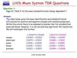
This presentation discusses the dressing test conducted for the LHCb Muon MWP chambers, including the threshold characteristics, test setup, performed tests, and results. It also covers the cross-check with cosmic acquisition and provides a conclusion.

E N D
Dressing Test for the LHCb Muon MWP Chambers LECC 2006 Valencia Speaker: Rafael Antunes Nobrega (INFN Roma1) INFN Roma1: V. Bocci , R. Nobrega INFN Roma2: G. Carboni, A. Massafferri, E. Santovetti
Indice • Chamber & Front-end Electronics • Threshold Characteristics • Test Setup • Performed Tests • Auto-Injection (External Counters) • Threshold Scan Noise Measurement • Noise Rate @ Nominal Threshold • Systematic Errors • Tested Chambers Results • Cross-Check with cosmic acquisition • Conclusion Threshold Scan
Chambers & Front-end ElectronicsIntroduction 2&4 gaps chambers LHCb Muon System has foreseen 19 geometrically different MWPCs. Depending on its type, chamber capacitance can vary from roughly 40pF to 250pF and signal can be read from anode and/or cathode connections. Due to the later requirement, CARIOCA has been developed to process both polarities by implementing 2 different pre-amplifiers at the very ASD input stage. They show slightly different signal responses depending on the chosen polarity operation. The on-detector circuitry is composed of three boards: OR-PAD, Spark-Protection (SPB) and CARDIAC. The first two boards make use of passive components while the third board processes and digitalizes chamber signals. 4 gaps chamber illustration • Front-end main feature • CARIOCA • 8 input/output lines • signal amplification • tail cancellation • base line restoration • digitalization into LVDS lines. • DIALOG • read up to 16 CARIOCA channels outputs • 16 8-bits DACs which provide threshold voltage • width and delay adjustment • Masking • 24-bits scaler to each input channel • auto-injected signals • access via LVDS-based I2C protocol The detector capacitance determines the noise level since it acts as a series noise source.
Front-endMain Characteristics Overview of the ASD main characteristics • Max. Rate ~ 10-25 MHz (depending on polarity) • Sensitivity • From 16 to 8 mV/fC • ENC – Equivalent Noise Charge • From 0.3 to 2 fC • Offset • From 740 mV to 860 mV (range of about 10 fC) • must be measured (Thresholds – one per channel) Offset
Front-endMain Threshold Characteristics DTV CARIOCA discriminator makes use of a Differential Threshold Voltage (DTV) circuit (8 in total). It is able to provide a differential threshold (VrefA - VrefB) from an unipolar reference voltage (Vref). Apart from the offset spread we have: • Minimum detectable charge: • this value can vary from roughly 2 fC to 4 fC depending on the input capacitance (rms for a single input capacitance was shown to be around 0.3-0.4 fC). • Residual Bias (minimum detectable voltage – discriminator characteristic) • In principal this value is not correlated to the input capacitance and has a value of about ResBias = 35 mV ± 5.5 mV (Error of ~0.4 fC). • ReaBias used from LHCb Database to minimize error. Threshold Scan
8 channels CARIOCA CARIOCA DIALOG DIALOG LVDS CARIOCA CARIOCA 16 channels 8 channels 8 channels Test Setup • Dressed Chamber (DUT) • Control FEB via I2C (Service Board & CANopen) • Internal Counters (FEB feature) • External Counters (ACQ & Gate Boards and USB-VME) • BarCode Reader UNDER TEST • PC (WIN, Visual C++ & ROOT) • Barcode and Test Program USB Service Board (SB) is the board which will control the front-end electronics in the experiment. ACQ is a VME module with 64 counters on it. The Gate Board translates the SB gate signal sent to the front-end to be used also by the ACQ. Gate Signal LVDS FE ACQ TTL
Program (Visual C & ROOT) Barcode Complete Test Results Assembling Phase OutputPar.dat Diagnostic.log DATABASE Chamber Barcode X Front-end Barcode Get FEB parameters from DATABASE
Performed Tests • Verify if Cables are Switched • Auto-Injection (External Counters) • test of output drivers (LVDS) • Threshold Scan • noise presence evaluation • noise rate x threshold • Noise Rate @ Nominal Threshold • evaluation of level of noise at nominal threshold
Cable Checking and Auto-Injection Test Cable Checkng Check if cables are switched by injecting pulses to specific channels and reading external counters Auto-Injection Test Check if FE is working properly (auto-injection, internal counters, output lines) Inject N pulses to all channels Read internal & external counters Comparison DIAGNOSTICS
Found the ‘offset’ parameter If ‘offset’ is not found – ERROR If number of noise points is < 3 (on side) – ERROR This number can be adjusted to detect open channels If ‘offset’ in not within limits (expected) – ERROR Threshold ScanNoise Presence Valuation & Offset The detector capacitance determines the noise level since it acts as a series noise source. Most of the bad channels are detected with this simple diagnostics. Acceptance window
Qn = 1.2 fC Qn = 0.7 fC 2 2 2 2 Qn = 1.2 fC Qn = 0.7 fC Threshold ScanRate-Method - Noise Rate x Threshold Previous studies has shown that the assumption of a Gaussian amplitude distribution of the noise is, in first approximation, reasonable. The noise rate versus threshold level can be represented as following if we consider the bandwidth of the circuit. Vertex frequency can provide information about FE circuit bandwidth. The circuit bandwidth is known so it is a good parameters to have a feedback of the test setup. For CARIOCA this value is around 10-25 MHz (depending on polarity) NOT DETECTABLE REGION The slope of noise versus threshold curve allows an measurement of the noise in Volts (the threshold is set in Volts) and consequently the estimation of capacitance at the FEB inputs (Cdet). measured 107 less sensitive region
Threshold ScanRate-Method - Noise Rate x Threshold Measured Mean from Expected (3 RMS of acceptance) Expected value to chamber under test L If L < 3 RMS - OK Usually it happens only if there is something wrong with setup WARNING Cdet ERROR Chamber Channels Cdet (Noise) Evaluation (3-4 RMS of acceptance) 3 RMS window Worst Case Histo of 48 channels 4 RMS limit
Noise Rate @ Nominal Threshold Previous studies of LHCb Muon Group has shown that chambers can have electronics noise up to few kHz • Threshold Test Values • Negative Chambers • 10 fC • 12 fC • 14 fC • Positive Chambers • 6 fC • 7 fC • 8 fC threshold OK WARNING ERROR OK WARNING ERROR If Noise Rate < 1000 Hz All data is kept for further analysis if needed
Output Parameters • The main parameters available for visualization are: • Slope (mV) • Offset (mV) • Cdet (pF) • Threshold @ 100 Hz (from noise curve) • Noise Rate @ 3 levels of thresholdaround the nominal threshold • ENC (fC) • In this file it is also reported the values of the LHCb FEB test database (Potenza) Max.Noise Rate Slope Offset threshold^2
Diagnostics Results • Diagnostics are reported on file. • To track down the problematic channels the front-end board addresses and channels are indicated together with result values. • Keep history of tests. • If more than one test is done to the same chamber we intent to not delete the previous information but add the new test information on the chamber file.
(fC) M2R3 Estimation of Measurement Error • One single channel tested for 5 different capacitances (47, 56, 100, 180 and 220 pF) (100 measurements to each capacitance) • 5 16-channels capacitor boards were built • The results showed that it is possible to measure a channel input capacitance with a precision of RMS= ~0.04 fC (~5 pF) • but this is a hard task since we would need a calibration curve for each channel. • The bottom plot shows linearity behaviour of equivalent noise charge versus ASD input capacitance. It must be noted that for the bottom graph horizontal error bars represent 5% capacitance tolerance while vertical error bars represent Gaussian standard deviation. When evaluating different channels of a group of boards the system looses precision due to spread on FE characteristics, RMS = ~0.3 fC (about 20 pF). It is enough to evaluate single channels. Tested chambers (fC)
INFN Chambers • ~ 130 Chambers TESTED • ~ 200 Chambers at LNF • < 100 Chambers (M2-M5) STILL TO BE BROUGHT TO LNF
Tested ChambersLNF - Frascati After cuting bad chambers 128 Output Files Analyzed / 119 Good LNF 59-M5R4, 22-M3R3 Firenze 41-M5R4 Ferrara 06-M5R2 LNF M5R4 (~230pF) LNF M5R3 (~130pF)
Tested ChambersFirenze e Ferrara FIR M5R4 (~230pF) FER M5R2 (~120pF)
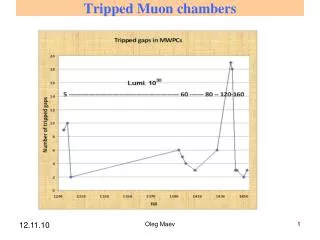
Low. Eff Cross-Check with Cosmic Acquisition • Acquisition using cosmics was done on the tested chambers. • Only one dead channel found, due to transportation (Frascati >> CERN). • A new problem that was not being detected by our system was found • on less than 0.5% of the channels. • Studies has shown that those channels have an particular shape (Threshold x Noise Rate). • The characteristics of the circuit is altered (?). • Low Eff. on cosmic acquisition • Rate capability (in this case it might not be detected for low capacitance chambers) • Lower minimum detectable voltage >> In principal a simple check on the curve shape or optimization of diagnostic parameters would be enough but we have to see for low capacitance chambers. Normal shape Cosmic Acquisition Malfunctioning channels
Goal of Project The goal of this project is to implement an automatic and fast system to be used also for non experts → mass production test. Chambers that do not pass on the tests must be seen more carefully by experts (by now when we have a bad channel, it is solved at the same moment and than a new test is done). We aim to reduce drastically the number of chambers to be rechecked at the end.
Conclusion • Goal – Automatic and fast (5-10 minutes) system has implemented to test a big number of chambers • Project is already in use to test the INFN MWPC Chambers • ~130 chambers tested • System has shown to be very efficient • Test of high capacitance chambers (M5R4) gave positive feedback • Tests of low capacitance chambers will give us important feedback • Cross-check with cosmic acquisition test has been positive • Only 0.5% of channels has presented an unexpected kind of problem and probably it will be possible to detect it on an upgraded version • We are studying it and diagnostics will be upgraded