Download
1 / 36
360 likes | 523 Views
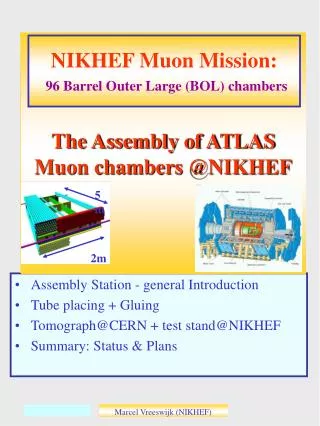
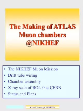
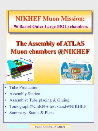
5m. 2m. The Assembly of ATLAS Muon chambers @NIKHEF. NIKHEF Muon Mission: 96 Barrel Outer Large (BOL) chambers. Tube Production Assembly Station Assembly: Tube placing & Gluing Tomograph@CERN + test stand@NIKHEF Summary: Status & Plans. Tube wiring + QC. Drift tubes:

E N D
5m 2m The Assembly of ATLAS Muon chambers @NIKHEF NIKHEF Muon Mission:96 Barrel Outer Large (BOL) chambers • Tube Production • Assembly Station • Assembly: Tube placing & Gluing • Tomograph@CERN + test stand@NIKHEF • Summary: Status & Plans Marcel Vreeswijk (NIKHEF)
Tube wiring + QC • Drift tubes: • Extruded aluminum drift tubes (3cm) • Wire (50mm gold-plated tungsten) positioned by two end-plugs Endplug • QC on drift tubes, specs: • Wire position: |Z,Y|<25mm • Wire tension=> • frequency 27.2+-1.4 Hz, RMS<0.3Hz • Leak rate: <2.5 10-8 bl/s • HV check: <20nA @3500V • Tube Length +-0.5mm Marcel Vreeswijk (NIKHEF)
Drift Tube Coil EndPlug RMS: ~6mm QC-Wire position • Wire position Spec: • |Y,Z|<25mm For BOL-1 All tubes checked In future: Fast pre-check endplug Rejection <<1%: 2 tubes with Z> 50um (1 checked: no twister) cut cut No twister to position wire Marcel Vreeswijk (NIKHEF) s
QC-Wire tension • Quality Control on drift tubes, specs: • Wire Frequency: 27.2 (+-1.4)Hz, RMS<0.3Hz Principle: Lorentz force on current through wire causes vibration Drift tube Frequency RMS: 0.17 Hz Horse-shoe magnet Tension re-measured just before gluing on table (checks creep + broken wires) Rejection <<1%. Marcel Vreeswijk (NIKHEF) s
QC-Leak Rate + HV • Quality Control • Leak rate: <2.5 10-8 bl/s • HV: < 20nA at 3400V Principle: HV Drift tube (1% He) Vacuum chamber He sniffer Automated ‘Matrix’ for 80 tubes Marcel Vreeswijk (NIKHEF) s
QC-Leak Rate Leak-rate Leak rate is low: from 3bar to 2bar takes several years!! spec Rejection 1% (!) 10-6 bl/s • 3 tubes inspected: • 1 physical hole in aluminum • 2 ‘dust’ on O-ring Marcel Vreeswijk (NIKHEF) s
QC-HV • A typical ‘Matrix’ fill Tube with excess<<spec. Measure 5hrs. Average last 3hrs Current (nA) Gauge Tube nr Marcel Vreeswijk (NIKHEF) s
Chamber Assembly • Spacer monitored by RASAS Situation mid 2000 No Flexo In-plane lens NIKHEF Comb longbeam RASAS tower Xplate In-plane mask Frascati comb ‘Ear’ with sphere and RASAS-MASK Sphere tower with changeable block to adapt to tube layers West side has expansion length o 0.1m in Xras Marcel Vreeswijk (NIKHEF) s
‘RASAS’ Monitors Monitor positioning during assembly by RASAS monitor: Support ‘ear’ which holds the mask xplate Changeable blocks Block 3 The RASAS tower which holds the camera and lens Block 2 RASAS Height (mm) Ypitch 26.011mm Scatter 5um Block 1 Measured temperatures explain (small) drift Marcel Vreeswijk (NIKHEF) s
Xplate 2.4m fixed Temperature Stability • Aluminum expands 24um/ oC/m, Granite 7um/ oC/m • Under normal conditions, temperature stable within +-0.4 oC • Test case: increase temp. by 1 oC: check RASAS monitors Free to expand monitor granite Raw: 50um Correct for AL 24um/ oC/m + Correct for granite 7um/ oC/m Marcel Vreeswijk (NIKHEF) s
Precision Mechanics • intrinsic accuracy better than 10um • Positioning combs and sphere holders • Tools: • Laser + optics (straightness combs), • silicon sensor (to line up combs), • Slof (height-meter), • tilt-meters (check Torque), • Balmonitor (dZ between multilayers) The quantities which affect the wire positions are checked and found to be precise within 10um Granite table has sag of 25um + 10um light on/off West side has expansion length o 0.1m in Xras Marcel Vreeswijk (NIKHEF) s
Assembly Station • The Balmonitor is a Cross-Plate equipped with lenses. Each lens is combined with a ‘fork’ on the combs to form a RASNIK system • The Balmonitor measures the Z and Y difference between Sphere tower and Comb between North and South. (Z difference between Multilayers) • Additionally the Balmonitor is used to check for height difference between sphere towers at the reference and non-reference side (West/East) West side has expansion length o 0.1m in Xras Marcel Vreeswijk (NIKHEF) s
Tube Placing I Place tubes (with clocking pins) on combs (Re-)Measure Wire Frequency Run Final-OK program IF all tubes OK, follow placing scheme Frequency Small calibration problem Specs: RMS< 0.3 Hz BOL1: 27.2+-0.7 Hz Later: 27.2+-1.4 Hz FOK program ensures 72 tubes are OK Tube numbers and positions stored in dbase Marcel Vreeswijk (NIKHEF) s
Tube Placing II Fix gas jumpers -length differences get ‘neutralized’ Spec=-+0.5mm (FE-cards+ground foil) Marcel Vreeswijk (NIKHEF) s
Tube Placing QC Vacuum on Remove clocking pins, loosen gas jumpers Check precision: Guido Laser (not automated yet) Y deviation (mm) Tube Position (South) Tube Position (North) Marcel Vreeswijk (NIKHEF) s
Sagcompen-sation tower Additional weight for balance Sag Compensation ‘Dry’ Check Position spacer (+tube layers) on the table Check sag-compensation (not automated yet) Strip Actual Gluing: Chamber is pre-positioned: 1mm strips under sphere blocks+50% sag-comp. Then strips are removed + 80-90% sag-compensation Marcel Vreeswijk (NIKHEF) s
Sag Compensation • Xplate sag before and after compensation Chamber up Chamber (upside) down Understood within +-10mm After sag adjustment we observe (almost) symmetric sags for chamber up and down positions-> no stress Marcel Vreeswijk (NIKHEF) s
tube tube tube tube tube Gluing Tube diameter 3cm Distance 65mm 2 x glue units 2x3 glue nozzles automated 50mm tape on Bessel points Central rope, Glu: 2019 Side rope, Glu: 2011 Marcel Vreeswijk (NIKHEF) s
Gluing BOL Marcel Vreeswijk (NIKHEF) s
Monitoring badly positioned -> action! Compensation on • 3 systems monitor chamber during assembly: • RASAS system (include temperature check) • In-Plane system • RASNIKS on cross-plates (sag) 50mm Sag 0 Monitoring system->actions not yet user friendly…. time Marcel Vreeswijk (NIKHEF) s
The BOL-0 The BOL-0 was mechanically finished Dec 5th 2000 The BOL 1 was finished yesterday Marcel Vreeswijk (NIKHEF) s
Power Outage- BOL1 Power outage Amsterdam, during curing of layer 5 Chamber immediately covered with foil (sag compensation remained on + vacuum probably ok No indications for damage Marcel Vreeswijk (NIKHEF) s
NW NE Global X Global Z, RASAS X SW SE Gluing BOL-1 • RASAS monitors Global Z Global Y (up) • Positioning spacer appears sufficiently accurate • However, differences with and without tubes (+glue) in combs --> touch • (Y pitch dangerously small) Marcel Vreeswijk (NIKHEF) s
The road to BOL-1 • From 1st tube layer to 6th tube layer took 14 days (spacer not counted) • With optimal/parallel preparation the present scheme would allow a 7 day production cycle • Infrastructure and manpower-> • 10 working-days/chamber Marcel Vreeswijk (NIKHEF)
Test @CERN inTomograph (BOL0) Analysis of Martin Woudstra Wire positions RMS 16mm Marcel Vreeswijk (NIKHEF) s
Parameters BOL0 • Zpitch wires: • 30.0354mm (30.0353 expected) • Ypitch wire-planes: • 26.026mm (26.011 expected). Especially between two inner layers we have a larger pitch. Inelastic deformation during gluing? • dY multilayers ~75mm. • Hard to understand. ALL chamber scanned at CERN have deviations in this parameter?! • dZ multilayers ~12mm. • We expected deviations of this order, based on Balmonitor measurements • Relevant Parameters (goal 20mm): • RO side s=15.8mm HV side s=16.1mm Marcel Vreeswijk (NIKHEF) s
Test stand DATCHA Like cosmic ray setup at CERN (shutdown in 2000) Test of alignment principle with prototype muon sector, using cosmic tracks --> 10mm on sagitta Marcel Vreeswijk (NIKHEF) s
Test stand @NIKHEF • Tests five chambers using cosmic rays (end 2001) • Checks wire positions • Checks DCS + DAQ Trigger modules, consisting of 50cm iron, with two layers scintillator. Ecut>1GeV Expected rate: 100Hz Marcel Vreeswijk (NIKHEF) s
Status & Plans • Finished BOL-0 at NIKHEF (dec. 5th 2000) with high mechanical precision (16mm RMS) • Quality Control Tube Assembly automated • Production of tubes started May 2001 • First chamber, BOL1, produced! Difficulties due to small Y pitch. • Automate steps+QC chamber assembly • Cosmic ray setup end 2001…. Marcel Vreeswijk (NIKHEF)
Expected shifts Marcel Vreeswijk (NIKHEF) s
NW NE Global X Global Z, RASAS X SW SE Gluing BOL-0 • RASAS monitors Global Z • Relatively large Z movement layer 6 (spacer floats on glue?) Lever arm in stacking block Global Y (up) • Stability in Y appears good Marcel Vreeswijk (NIKHEF) s
Start glue Start glue Gluing BOL-0 • Guido laser test indicate tube heights in combs <10um. • Stability Xplates during gluing Layer 1 Yrasnik=2 x Sag Layer 1: dSag=7um Layer 2 Start glue Layer 3 Layer 2: dSag=10um • The sag of the xplates in layer 1 and 2 change in time. Glue crimp? Temperature? • Layer 3,4,5,6: Sag stable Marcel Vreeswijk (NIKHEF) s
Gluing BOL-0 • In-Plane and Xplate monitors • X-inplane very stable • Y-inplane alternates with chamber orientation, because off granite sag of 30um down down up up Cross-plate sag. For chamber up (down) positions, a negative (positive) sag points down. Marcel Vreeswijk (NIKHEF) s
BOL-0 Thickness Multi-layers BOL0 has tape between tubes at one side Much work.. 2 layers • Tubes press glue away? • Tubes deform? • Affects precision praxial platforms! 3 layers Marcel Vreeswijk (NIKHEF) s
Xplate 50um 400um Yrasnik= 2 x sag Chamber sag Xplate sag BOL-0 Heat Studies (No flexoos in BOL-0) The BOL-0 was covered with heat blankets, producing 50W/m2 Inplane Yrasnik= 2 x sag Gradient between MLs: 2.5 to 4 oC Sag of Chamber: 200um 50 to 80 um/oC= acceptable Sag of xplate: 25um 6 to 10 um/oC = acceptable Marcel Vreeswijk (NIKHEF) s
tube Gluing BOL-0 • Result for side (106) and central (103) ropes Central rope Central rope Central rope Central rope Central rope, sometimes bad (stability glue unit?) Marcel Vreeswijk (NIKHEF)