Download
1 / 16
160 likes | 314 Views
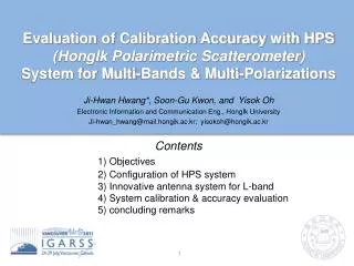
Evaluation of Calibration Accuracy with HPS (HongIk Polarimetric Scatterometer) System for Multi-Bands & Multi-Polarizations Ji-Hwan Hwang*, Soon-Gu Kwon, and Yisok Oh Electronic Information and Communication Eng., HongIk University Ji-hwan_hwang@mail.hongik.ac.kr; yisokoh@hongik.ac.kr

E N D
Evaluation of Calibration Accuracy with HPS • (HongIk Polarimetric Scatterometer) • System for Multi-Bands & Multi-Polarizations • Ji-Hwan Hwang*, Soon-Gu Kwon, and Yisok Oh • Electronic Information and Communication Eng., HongIk University • Ji-hwan_hwang@mail.hongik.ac.kr; yisokoh@hongik.ac.kr • Contents • 1) Objectives • 2) Configuration of HPS system • 3) Innovative antenna system for L-band • 4) System calibration & accuracy evaluation • 5) concluding remarks
Objectives • For a comparison study on earth observation with satellite SAR system at various frequency bands, requirements of multi-bands / polarizations ground based scatterometer continuously are increasing. • the existing HPS(Hongik Polarimetric Scatterometer) system basically support L-,C-,X-bands and full-polarizations (vv-, vh-, hv-, hh-pol.), however, those are separated system. • this study shows configurations of 1)integrated system for multi-bands with single platform and evaluates an accuracy of 2)system calibration in the field experiments. IGARSS 2011
Configuration of HPS system 1) Boom structure (8m) : movable platform 2) Head part : it’s consist of sensor (OMT+Ant.) and incident angle control 3) Sub-circuit : this circuit achieves two functions of frequency converting and switching for full-polarization 4) DAQ, Graphic User Interface : HPS is basically network analyzer based system, Agilent 8753E and controlled by GUI [1]P. O’Neill, et al, “Survey of L-Band Tower and Airborne Sensor System Relevant to Upcoming Soil Moisture Missions,” IEEE Newsletter Geosci. Remote Sensing, Jun. 2009. IGARSS 2011
Configuration : Head Part • To implement the motion control(θ,Ф), head part is composed of 3 step motors and inclinometer sensor.Incident angle (θ) : tolerance0.2° Input Inc.angle (Ain) (1) Step motors (3ea) Meas. Curr. Ang. (An), n=0 MOVE Ang. (Amove=An-Ain) Meas. Ang. (A(n+1)) Amove Meas. Ang. (An), n=1 |An-Ain|<0.2° (n+1) No Yes (2) Inclinometer sensor (2-axis) Set position (destination) [2] J.-H. Hwang, S.-M. Park, S.-G. Kwon, Y. Oh, “Study on the calibration of a full-polarimetric scatterometer system at X- band (in Korean)”, KIEES, Apr. 2010. IGARSS 2011
Configuration : sub-circuit • Switching circuit offers full-polarimetric signal without mode change of network analyzer (Agilent 8753E) and switch the path for each bands • Frequency conversion and amplifier circuit only for X-band minimize signal distortion and path loss through 7m RF cable : (9.65GHz to 1.25GHz, gain 32dB p1dB 20dBm) Pol. indicator Tx-path RF-cable 7m Rx-path IGARSS 2011
Configuration : GUI & DAQ • GUI software controls whole measurement system: • ex) inc. angle, time gating, Tx power level, automatic meas., system cal. File header Full-pol. Measurement data Incidence angle IGARSS 2011
H-pol. Innovative Ant. System for L-band (type 1) • the existing ant. system (horn ant. + OMT) for L-band is too bulky to be installed in HPS platform. So, we suggested two types of compact OMT. Common mode port H-pol. • Type 1 OMT is minimized by newly • designed compact T-junction Conducting post Waveguide taper < OMT with Compact T-junction> Reduced total size to about 56% V-pol. < Commercial class 1 OMT > Waveguide taper waveguide T-junction [3] J. -H. Hwang, S.G. Kwon, Y. Oh, “orthomode transducer using trapezoidal waveguide”, Patent in Korea, 10-2010-0090749 (in progress). V-pol. Total length =75cm, IGARSS 2011
Stepped - horn antenna λ (length: 300mm, 1.26 0 aperture: 450 450mm 2 ) × Proposed new OMT (length: 560mm, 2.35 λ ) 0 Innovative Ant. System for L-band (type 2) • Total length of new OMT is about 86cm (commercial OMT 1.35m) • It achieved reducing the OMT size to about 62% and also keeping the comparable performance with the same class OMT structure A1 1.35m (Class 1) A2 0.86m (Class 3) [4] J. -H. Hwang, Y. Oh, “Compact OMT Using Single-Ridged Triangular Waveguide”, IEEE MWCL, 2011. [5] J. -H. Hwang, S.G. Kwon, Y. Oh, “orthomode transducer using waveguide with 4-splitted triangular cross section”, Patent in Korea, 10-2010-0091816 (in progress). IGARSS 2011
System calibration (Single Target Cal. Tech.) • HPS system was calibrated using STCT at each frequency bands. • to calibrate HPS system, measured data of ref. and test targets are needed, and we can calculate the calibrated scattering matrix of test target. Mie exact solution s0 : theoretical [S0] of ref. target (sphere) m0 : measured [M0] of ref. target (sphere) mu : measured [Mu] of test target (C.R.) spg : calibrated [S] of test target (C.R.) 2DTST (2D target scanning technique) This method offers ‘well-aligned’ data [5] K. Sarabandi, and F. T. Ulaby, “A convenient technique for polarimetric calibration of single-antenna radar systems,” IEEE Trans. Geosci. Remote Sensing, Nov. 1990. IGARSS 2011 IGARSS 2011
System calibration (2D Target Scanning Tech.) • 2DTST: this technique can measure full-pol. freq. responses of ref. / test targets and graphically choose the ‘well-aligned’ center data. • Concept view of gird system for 2DTST Max point (-1,1) ~ boresight Scan resolution ~1˚ [4] J. -H. Hwang, S. -M. Park, Y. Oh, “Calibration Accuracy Enhancement in the Field Experiment with a Ground-Based Scatterometer”, IGARSS 2010, Aug. 2010. IGARSS 2011
10 10 0 [dBsm] 0 -10 q -10 p s -20 -20 RCS, -30 -30 -40 -40 1 1.1 1.2 1.3 1.4 1.5 9.4 9.5 9.6 9.7 9.8 9.9 freq. [GHz] freq. [GHz] System calibration (multi-bands/full-pol.) • These results are calibrated Full-pol. freq. responsesusing STCT and 2DTST • to evaluate calibration accuracy, conducting sphere of 30cm diameter and 30/45cm TCR were used as REF. and test target, respectively. L-Band C-Band X-Band 10 theory un-cal. 0 cal. s -10 v v s v h -20 s h v s -30 h h -40 5.1 5.4 5.2 5.3 5.5 freq. [GHz] After calibration, effective isolation levels improve more than about 10dB IGARSS 2011 11
0.5 1 0 0.5 -0.5 0 -1 -1.5 -0.5 -2 -1 -2.5 -1.5 -3 5.1 5.2 5.3 5.4 5.5 9.4 9.5 9.6 9.7 9.8 9.9 freq. [GHz] freq. [GHz] Evaluation of Cal. accuracy • Calibration accuracy can be defined to RMS value of the norm of residuals, which is a degree of similarity between two data arrays. : RMS norm of residuals L-Band C-Band X-Band ~ 0.4dB 1 0 Cal. resid. -1 Cal. accuracy ~ 0.3dB ~ 0.3dB un-cal. resid. -2 Rasiduals [dB] -3 -4 -5 -6 1 1.1 1.2 1.3 1.4 1.5 IGARSS 2011 12 freq. [GHz]
L-Band C-Band X-Band 60 60 60 60 60 60 s : [dB] s : [dB] s : [dB] v v v v v v 50 50 s : [dB] 50 50 50 s : [dB] 50 s : [dB] h h h h h h f - f : [deg] f - f : [deg] f - f : [deg] h h v v h h v v h h v v 40 40 40 40 40 40 Cal.Error: mag [dB] Reliability zone ~ 6.5° Phase error [deg] ~ 5° ~ 3° 30 30 30 30 30 30 20 20 20 20 20 20 10 10 10 10 10 10 0 0 0 0 5 10 15 0 5 10 15 20 25 30 0 5 10 15 20 25 30 Off-Center Angle [deg] Off-Center Angle [deg] Off-Center Angle [deg] Evaluation of Cal. accuracy • These results show the spatial changes of calibration accuracy depending on the degree of mis-alignment between antenna and test target. • we can assign ‘Reliability zone’, which is ‘well-aligned’ region to guarantee the calibration accuracy of 0.5dB in field experiments. *Note: It depends on meas. antenna radiation pattern: HPBW (29°/35°, 25°/29°, 12°/13°), E-/H-. Phase error does not exceed about 7˚ in all frequency bands. IGARSS 2011
Concluding remarks • HPS system for multi-bands & multi-polarizations integrated to single-platform and, especially, the newly designed antenna + OMT system for L-band is applied. • To calibrate scatterometer system, STCT and automatic 2DTST were used, and these results agreed well with theoretical RCS. • ‘Reliability Zone’, to guarantee 0.5dB calibration accuracy, are 6.5˚, 5˚, and 3˚ in L-,C-,X-bands, respectively. • This ground-based HPS system will be continuously used for comparison study of satellite SAR system as a test-bed. Thanks, do you have any questions?? IGARSS 2011
Appendix 1. (off-center error rate) • to verify the off-center error caused by mis-alignment, we measured surroundings from the center of ref. target. • we assume that the well-aligned center data, maximum position between antenna and target, have highest accuracy and reliability. where, ‘corr.’ is correlation coefficient of centered and off-centered meas. data arrays of ref. target. < e.g., Off-center errors of X-band > IGARSS 2011
Appendix 2. : Backsacttering coef.(σ˚) in tidal flat + pattern cal. [M0] C-band, 2010.08.16 C-band: oysterfield Oyster field Mud area X-band, 2010.08.17 X-band: mud area Oyster field Mud area IGARSS 2011