Microcontroller Interfacing: Selected Topics
Microcontroller Interfacing: Selected Topics. LCD Panel Display One-Wire ™ Bus (Temperature Transducer) Common Input Devices and Displays Common Output Devices and Actuators. Optrex and Hitachi LCD Panel Display. LCD Panel Pin Description.

Microcontroller Interfacing: Selected Topics
E N D
Presentation Transcript
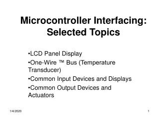
Microcontroller Interfacing: Selected Topics LCD Panel Display One-Wire ™ Bus (Temperature Transducer) Common Input Devices and Displays Common Output Devices and Actuators
LCD Panel Pin Description • DB7:0 – Data Bus. 8-bit data bus for both display commands AND display ASCII data. • RS – Register Select. Set to 0 to indicate a command on Data Bus and 1 to indicate ASCII data on Data Bus. • RW-Read/Write. Set to 0 for write to data bus and 1 for read from data bus. We shall strap this pin to 0, so it is permanently enabled for WRITE to data bus mode, in order to simplify our interface. • E – Enable (data clock). This pin must rise at least 140 ns after RS and R/W have been set up, and it must fall at least 195 ns after DB7:0 has been set up. Furthermore, DB7:0 must be held at least 10 ns after E falls. Also, E must be high for at least 450 ns.
The setting of RS and R/W allows us to (1) write data to Display RAM (DR) (2) Read datafrom DR (3) Write commands to the display (4) read the busy flag and current value of the address counter (which controls position of character being written to DR.)
Ex. Prints letters “abcd…st” on 20X2 line LCD panel //LCD Display Module Interfacing Example in Hi-Tech PICCLITE C //Number of PIC pins used: 6 (RB5 - RB0) //This example works for any LCD Module made by Optrex, Hitachi, etc. //Two 4-bit nybbles are sent one after the other from the PIC16F877 to the LCD interface, //as explained in Microchip Application Note AN587 (DS00587B - page 3-205) //Chip Type: PIC16F877 //Clock Frequency: 13.5 MHz //Written by KEH on 11/01/2003 //LCD Display Type: 20 char X 2 line //*********************************************************************** //LCD Display Module connections to the PIC // LCD Pin LCD Pin # PIC Sig PIC Pin # // 1 GND --- --- // 2 Vcc --- --- // 3 Vee (Gnded for full contrast) // 4 RS RB5 P38 // 5 R/W* (Gnded, since we will only write to LCD module) // 6 E (data strobe)RB4 P37 // 7-10 DB0-DB3 (Not used) --- // 11 DB4 RB0 P33 // 12 DB5 RB1 P34 // 13 DB6 RB2 P35 // 14 DB7 RB3 P36 //***********************************************************************
#include <pic.h> #define RS RB5 #define RSCMD 0 #define RSDTA 1 #define E RB4 void initialize_lcd(void); void delayms(unsigned char); void sendnyb(unsigned char); void sendbyte(unsigned char); void main(void) { unsigned char j; PORTB = 0; TRISB = 0xC0; // Make RB5-0 all outputs initialize_lcd(); RS=RSDTA; for(j=0;j<20;j++) sendbyte(j+0x41); RS=RSCMD; sendbyte(0b10101000);//Set DDRAM address command. Format (1 a a a a a a a ) //Set DDRAM address to 0x28 = 40. This is the starting address of the 2nd row. RS=RSDTA; for(j=0;j<20;j++) sendbyte(j+0x61); for(;;) continue; }
void initialize_lcd(void) { //initializes LCD Display delayms(20); RS=RSCMD; E=0; sendnyb(0x3); // Function Set Command, Gen'l format: 0 0 1 DL N F * * delayms(0x5); // Note that DL = 1 => 8-bit interface mode //(Display must be started in 8-bit mode.) // Note that the N F * * (low order 4 bits) are not connected, //and may be any value. sendnyb(0x3); // Repeat a second time. delayms(0x1); sendnyb(0x3); // Repeat a 3rd time sendnyb(0x2); // Function Set Command - Now set interface to 4-bit (nybble) mode // Now that we are in nybble mode,send all 8 bits of each command via // two back-to-back calls to sendnyb( ). sendbyte(0x28); // Function Set Command Format: 0 0 1 DL N F * * // We just sent: 0 0 1 0 1 0 0 0 // DL=0 => 4-bit mode, // N=1 => 1/8 duty cycle // F=0 => 5 X 7 dot font sendbyte(0x08); // Display OFF command sendbyte(0x01); // Clear Display command sendbyte(0x06); // Entry mode set command format: 0 0 0 0 0 1 I/D S // I/D = 1 => Increment display addr ptr. // S = 0 => Do not shift (scroll) display sendbyte(0x0C); // Display ON command }
void delayms(unsigned char nrms) { // Uses Timer #2 to delay the nr of ms specified assuming clock freq = 13.5 MHz unsigned char i; T2CON=0b0000111; //Timer 2 tick time = (4/13.5 Mhz)*16 = 210.93 for (i = 0; i < nrms; i++) { TMR2=256-211; //Schedule TMR2IF flag to be set in 1 ms TMR2IF = 0; //Clear TMR2IF timeout flag while(TMR2IF == 0) continue; //Wait here for 1 ms, until TMR2IF flag is set } } void sendnyb(unsigned char sendval) { unsigned char portbval; portbval = PORTB; PORTB = (portbval & 0xF0) + (sendval & 0x0F); //Send out most sig 4 bits of sendval on RB3:0 delayms(1); E=1; delayms(1); E=0; delayms(1); } void sendbyte(unsigned char sendval) { sendnyb(sendval >> 4); sendnyb(sendval & 0x0f); }
DS18S20 Temperature Sensor Displayed on LCD Panel //DS18S20 (Dallas Semiconductor 1-wire Bus Temperature Sensor) Interfacing Example in PICCLITE. //PIC pins used: LCD Display: RB5 - RB0, Temp Sensor: RD0. //This example works for any LCD Module made by Optrex, Hitachi, etc. //This example is based on information in the DS18S20 datasheet //and Dallas Semiconductor App Note #162 "Interfacing the DS18x20 1-wire temp //sensor in a microcontroller environment //Chip Type: PIC16F877 //Clock Frequency: 13.5 MHz //Written by KEH on 11/01/2003 //LCD Display Type: 20 char X 2 line //*********************************************************************** //LCD Display Module connections to the PIC // LCD Pin LCD Pin # PIC Sig PIC Pin # // 1 GND --- --- // 2 Vcc --- --- // 3 Vee (Gnded for full contrast) // 4 RS RB5 P38 // 5 R/W* (Gnded, since we will only write to LCD module) // 6 E RB4 P37 // 7-10 DB0-DB3 (Not used) --- // 11 DB4 RB0 P33 // 12 DB5 RB1 P34 // 13 DB6 RB2 P35 // 14 DB7 RB3 P36 //***********************************************************************
#include <pic.h> #define RS RB5 #define RSCMD 0 #define RSDTA 1 #define E RB4 void initialize_lcd(void); void delayms(unsigned char); void lcdsendnyb(unsigned char); void lcdsendbyte(unsigned char); unsigned char one_wire_reset(void); void delay6us(unsigned int); void write_byte_one_wire(char); unsigned char read_byte_one_wire(void); void write_bit_one_wire(char); unsigned char read_bit_one_wire(void); void main(void) { unsigned char j; char scratchdat[10],msbtemp,lsbtemp; int temp,quot,lschar,middlechar,mschar,fractchar; PORTB = 0; TRISB = 0xC0; // Make RB5-0 all outputs TRISD0 = 1; //RD0 is pulled high through 4.7 kilohm external pullup resistor. initialize_lcd();
for(;;) { one_wire_reset(); write_byte_one_wire(0xcc); //skip ROM write_byte_one_wire(0x44); //Start Conversion delay6us(18); one_wire_reset(); write_byte_one_wire(0xcc); //Skip ROM write_byte_one_wire(0xBE); //Read Scratch Pad inside Temp Sensor lsbtemp = read_byte_one_wire(); msbtemp = read_byte_one_wire(); for(j=0;j<7;j++) scratchdat[j] = read_byte_one_wire(); temp = lsbtemp + (msbtemp<<8); if (temp & 1 == 1) fractchar = '5'; else fractchar = '0'; temp = temp>>1; //Get the temperature in degrees C instead of half degrees quot = temp/10; lschar = (temp - 10*quot) + 0x30; temp = quot; quot = temp/10; middlechar = (temp - 10*quot) + 0x30; temp = quot; quot = temp/10; mschar = (temp - 10*quot) + 0x30; RS=RSDTA; lcdsendbyte(mschar); lcdsendbyte(middlechar); lcdsendbyte(lschar); lcdsendbyte('.'); lcdsendbyte(fractchar); RS=RSCMD; lcdsendbyte(2); //Position Cursor at "Home Position" } }
void initialize_lcd(void) { //initializes LCD Display delayms(20); RS=RSCMD; E=0; lcdsendnyb(0x3); // Function Set Command, Gen'l format: 0 0 1 DL N F * * delayms(0x5); // Note that DL = 1 => 8-bit interface mode (Display must be started in 8-bit mode) // Note that the N F * * (low order 4 bits) are not connected, and may be any value. lcdsendnyb(0x3); // Repeat a second time. delayms(0x1); lcdsendnyb(0x3); // Repeat a 3rd time lcdsendnyb(0x2); // Function Set Command - Now we can set interface to 4-bit (nybble) mode // Now that we are in nybble mode, we can send all 8 bits of each command via // two back-to-back calls to lcdsendnyb( ). lcdsendbyte(0x28); // Function Set Command Format: 0 0 1 DL N F * * // We just sent: 0 0 1 0 1 0 0 0 // DL=0 => 4-bit mode, // N=1 => 1/8 duty cycle // F=0 => 5 X 7 dot font lcdsendbyte(0x08); // Display OFF command lcdsendbyte(0x01); // Clear Display command lcdsendbyte(0x06); // Entry mode set command format: 0 0 0 0 0 1 I/D S // I/D = 1 => Increment display addr ptr. // S = 0 => Do not shift (scroll) display lcdsendbyte(0x0C); // Display ON command }
void delayms(unsigned char nrms) { // Uses Timer #2 to delay the nr of ms specified assuming clock freq = 13.5 MHz unsigned char i; T2CON=0b0000111; //Timer 2 tick time = (4/13.5 Mhz)*16 = 0.474E-5 s //Nr Ticks in 1 ms = 1E-3 / 0.474E-5 = 210.94 ticks. for (i = 0; i < nrms; i++) { TMR2=256-211; //Schedule TMR2IF flag to be set in 1 ms TMR2IF = 0; //Clear TMR2IF timeout flag while(TMR2IF == 0) continue; //Wait here for 1 ms, until TMR2IF flag is set } } void delay6us(unsigned int nr6us) { unsigned int i; for (i = 0; i < nr6us; i++) { continue; } } void lcdsendnyb(unsigned char sendval) { unsigned char portbval; portbval = PORTB; PORTB = (portbval & 0xF0) + (sendval & 0x0F); //Send out most sig 4 bits of sendval on RB3:0 delayms(1); E=1; delayms(1); E=0; delayms(1); }
void lcdsendbyte(unsigned char sendval) { lcdsendnyb(sendval >> 4); lcdsendnyb(sendval & 0x0f); } unsigned char one_wire_reset(void) { unsigned char presence; RD0 = 0; TRISD0 = 0; //Pull DQ line low delay6us(80); //Wait for 480 US TRISD0 = 1; //Allow DQ to e pulled high delay6us(12); //Wait for 70 US presence = RD0; //Read state of DQ //(hopefully presence pulse being sent by temp sensor!) delay6us(68); //Wait 410 US for presence pulse to finish. return(presence); } unsigned char read_bit_one_wire(void) { unsigned char i; RD0 = 0; TRISD0 = 0; //Pull DQ low to start timeslot TRISD0 = 1; //Then let DQ line be pulled high. delay6us(1); //delay 15 us from start of timeslot i = RD0; return(i); //return value of DQ line (as set by temp sens) }
void write_bit_one_wire(char bitval) { RD0 = 0; TRISD = 0; //Pull DQ low to start timeslot if(bitval == 1) TRISD = 1; //Let DQ go high to write a 1 delay6us(18); //delay 108 us TRISD0 = 1; //Let DQ line go high to end cycle } unsigned char read_byte_one_wire(void) { unsigned char i; unsigned char value = 0; for(i=0;i<8;i++) { if(read_bit_one_wire()) value=value | 1<<i; //Read byte in one bit at a time delay6us(18); //Wait for rest of timeslot } return(value); } void write_byte_one_wire(char val) { unsigned char i; unsigned char temp; for(i=0;i<8;i++) //Write byte, one bit at a time { temp = val>>i; //Shift ith bit into LSB position temp = temp & 1; //Mask out LSB bit value write_bit_one_wire(temp); //Write it to temp sensor } delay6us(18); }
Liquid crystal twists light polarization by 90 degrees if no E field present, and by 0 degrees if an E field is present (since presence of E field straightens out the liquid crystal molecules). NOTE: The upper polarizer may be aligned to pass light with left-right polarization, while the lower polarizer may be aligned to pass light with a polarization that is into/out of the paper. Thus an AC waveform > 2.8V rms applied across electrodes, the LC is straightened out, and the segment is black, but if < 1.7V rms, the LC is twisted by 90 degrees, segment is white.
Liquid crystals encompass a broad group of materials that posses the properties of both a solid and a liquid. More specifically, they are a liquid with molecules oriented in one common direction (having a long range and repeating pattern-- definition of a crystal), but have no long range order in the other two directions. For example, all the molecules form lines are oriented in the Y direction (up and down), but they posses no common ordering in the x direction (disorder is also assumed in the Z direction). To more easily visualize this, think a 1-molecule-thick slice (one layer of molecules to be exact) of a block of liquid crystal material. If you examined another slice, the molecules would still be oriented in the Y direction, but they would be in different positions along the X-axis. By stacking millions of these thin slices, the Z direction is built up and as a result of the change in relative position on the x-axis, the Z direction has no long range order.
As a note of interest, polarizers are also one of the major reasons that LC displays require bright back lighting. The polarizers and liquid crystal materials absorb more than 50% of the incident light. As a result, even though the actual display is a very low power device, the power hungry back lighting makes a LCD module one of the primary causes of short battery life in notebook computers. Due to the fact that the LC material has optical properties and effectively bends light, the problem of viewing angle effects occur. When the user is not directly in front of the display the image can disappear or seem to invert (dark images become light and light images become dark). However, LC material and polarizer technology is rapidly improving and that improvement is showing up in brighter displays with greater viewing angles.
Liquid crystals must be aligned to the top and bottom pieces of glass in order to obtain the desired twist. In other words, the 90 degree twist is formed by anchoring the liquid crystal on one glass plate and forcing it to twist across the cell gap (the distance between the two glass plates) when contacting the second plate. Furthermore, The actual image quality of the display will be dependent on the surface alignment of the LC material. The method currently used for aligning liquid crystals was developed by the Dai-Nippon Screening (English= Big Japan Screening) Company. The process consists of coating the top and bottom sheets of glass with a Polyimide based film. The top piece of glass is coated and rubbed in a particular orientation; the bottom panel/polyimide is rubbed perpendicular (90 degrees for TN displays) with respect to the top panel. It was discovered that by rubbing the polyimide with a cloth, nanometer (1 X 10 - 9 meters) size grooves are formed and the liquid crystals align with the direction of the grooves. It is common that when assembling a TN LC cell, it will be necessary to eliminate patches of nonuniform areas. The two parameters required to eliminate the nonuniformities and complete the TN LC display are pretilt angle and cholesteric impurities. TN LC cells commonly have two problems that affect uniformity following assembly: reverse tilt and reverse twist. Reverse tilt is a function of the applied electrical field and reverse twist is common when no electrical field is applied. Reverse twist is eliminated by the introduction of cholesteric additives and reverse tilt is eliminated by introducing a pre-tilt angle to the LC material. The pre-tilt angle also determines what direction the LC molecules will rotate when an electrical field is applied. Pre-tilt angle can be visualized by considering the normal position of the LC molecule to be flat against the glass plate, by anchoring one edge and forcing the other upward by a specific number of degrees, a pretilt angle is established.
We have seen that a typical LCD display segment requires <1.7V rms “front-to-back” electrode to turn OFF the segment, and >2.8V rms to turn ON the segment. HOWEVER, the dc component of the “front-to-back” electrode voltage waveform MUST BE 0, or the LCD display will suffer permanent damage.
Note how the FP1 electrodes are passed under by one BP1, one BP2, one BP3, and one BP4 electrode. The same goes for the FP2, FP3, …, FP8 electrodes.
Note that the BP signals are always the same, and are shown below for 1:4 LCD display multiplexeing.
CUSTOM LCD Display Example using 1:4 Multiplexing: NOTE: Top two edge finger connections on left and right side are the four backplane connections. The rest of the edge fingers are frontplane connections which connect to exactly four segments.