PIC Microcontroller
DASL Motor Control Tutorial . PIC Microcontroller. In this PPT, all the materials covered up for the PIC microcontroller set-up would be studied. Preliminary skills: Knowing of basic C grammar and basic circuit analysis, and manual reading. . Introduction.

PIC Microcontroller
E N D
Presentation Transcript
DASL Motor Control Tutorial PIC Microcontroller In this PPT, all the materials covered up for the PIC microcontroller set-up would be studied. Preliminary skills: Knowing of basic C grammar and basic circuit analysis, and manual reading.
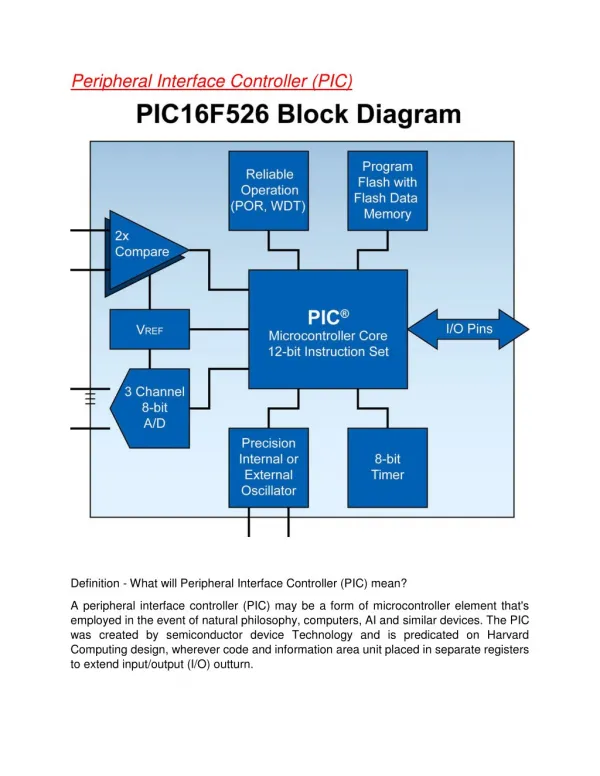
Introduction • PIC stands for “Peripheral Interface Controller”. • PIC is a family of Harvard architecture microcontrollers made by Microchip Technology. • PIC is programmed and run by MPLAB software. • In this tutorial, dsPIC33F - J128MC804 model will be used.
Peripheral Pins • As shown in Fig 1 and 2 (on next slide), all the peripheral PINs having different functions are commanded. Figure 1
Peripheral Pins Figure 2
Peripheral Pins • Each of peripheral PINs are commanded for different functions such as ADC, PWM, GIO(General Input & Output), QUART, QEI, etc. • In the next two slides, Table 1-1 shows the PIN names and what all the PINs are functioning for. • Depending on the purpose of a experiment, specific PINs need to be used and wired on the proper device.
Tips for Manual Search • All the manuals are provided on Microchip Technology’s website - http://www.microchip.com/, therefore you can easily search the functions and pins that you want to use. • Since all the provided manuals are PDF files you can easily search the key word by CTRL + F. • All the necessary manuals for motor control are provided on the last slide of this PPT.
Hardware • dsPIC33F - J128MC804 • MPLAB ICD2 & 3 (ICD 3 is recommended since extra works are necessary for the use of ICD 2) – A compiler sending the data from a computer to a PIC chip and vice versa. • The Base Electric Circuit – The properly designed electric circuit is needed to implement the PIC chip(In this tutorial, the electric circuit designed by one of the Hubo lab members will be used). ※ The procedure to make the base circuit will be discussed later.
Software Programs • MPLAB • C30 compiler • OrCAD • All the necessary software programs are provided on the blog. <MPLAB> <The interface of OrCAD>
Software Programs - MATLAB • This initial set-up is necessary for the time interrupt function in the main code.
Software Programs - MATLAB All the setups in ‘Init PWM’ allows motors to be controlled by PWM signals. You can manually change the settings based on the qualification of the motor that you use.
Software Programs - MATLAB ‘Init QEI’ function is set up to enable the users to read the data in real time from an encoder. You can get the data in a desired format by calculating a proper mathematical equation.
QEI & PWM • QEI stands for Quadrature Encoder Interface. In general, almost all of the encoders have two pins which generate A & B signals and as shown in Fig 3, signal A and B intersects consistently and this pattern is converted from the analog signal to digital signal by the QEI function in PIC chip. • There are four registers in QEI function, which are shown below: • Control/Status Register (QEIxCON) • Digital Filter Control Register (DFLTxCON) • Position Count Register (POSxCNT) • Maximum Count Register (MAXxCNT) • ※ ‘x’ is the number of a channel or a register.
QEI & PWM Figure 3
QEI & PWM Figure 4
QEI & PWM • PWM stands for Pulse-Width-Modulator. • PWM is generally used for motor control & LED lightness control. • PWM tutorial will be provided on the blog.
QEI & PWM (Channel) <MCPWM1 Module> <MCPWM2 Module> • MC • PTEN • Prescale • PTMOD • Pair mode • Pin enable • Iue • Dead time
QEI & PWM (Mode) Single pulse mode
QEI & PWM (Mode) Single Pulse Mode Free Running Mode
QEI & PWM (Mode) Count Mode
QEI & PWM (Pin Setting) As shown in the preceding slides there are two channels and for first module there are three sets of high and low signals and for second module there is only one set of the signals.
QEI & PWM (Dead Time) • It is enabled only in complementary mode. • To prevent a electric short in a circuit.
QEI & PWM (Enabling) • This register is used to enable PWM function.