Alignment
690 likes | 948 Views
Alignment. Visual Recognition. “Straighten your paths” Isaiah. Main approaches to recognition:. Pattern recognition Invariants Alignment Part decomposition Functional description. Alignment. An approach to recognition where an object is first aligned with an image using

Alignment
E N D
Presentation Transcript
Alignment Visual Recognition “Straighten your paths” Isaiah
Main approaches to recognition: • Pattern recognition • Invariants • Alignment • Part decomposition • Functional description
Alignment An approach to recognition where an object is first aligned with an image using a small number of pairs of model and image features, and then the aligned model is compared directly against the image.
Object Recognition Using Alignment D. Huttenlocher and S. Ullman 1st ICCV 1987
The Task • Matching a 2D view of a rigid object against a potential model. • The viewed object can have arbitrary 3D position, orientation, and scale, and may be touching or occluded by other objects • First the domain of flat rigid objects is considered: • The problem is not 2D as the flat object positioned in 3D • It still has to handle occlusion and individuating multiple objects in an image • Next – extension to rigid objects in general.
Aligning a Model With the Image For 2D recognition, only two pairs of corresponding model and image points are needed to align a model with an image. Consider two pairs, such that model point corresponds to image point and model point corresponds to image point . The 2D alignment of the contours has three steps: • The model is translated such that is coincident with • Then it is rotated about the new such that the edge is coincident with the edge • Finally the scale factor is computed to make coincident with
These two translations, one rotation, and a scale factor make each unoccluded point of the model coincident with its corresponding image point, as long as the initial correspondence of and is correct. • For 3D from 2D recognition, the alignment method is similar, requiring three pairs of model and image points to perform a three-dimensional transformation and scaling of the model.
The Alignment Method of Recognition Two stage approach: • First: position, orientation, and scale of an object are found using a minimal amount of information (e.g. three pairs of model and image points) • Second: alignment is used to map the object model into image coordinates for comparison with the image Given an object O in 3D and its 2D image I (perhaps along with other objects). Find O in the image using the alignment computation .
Assume that a feature detector returns a set of potentially matching model and image feature pairs P • Since three pairs of model and image features specify a potential alignment of a model with an image, any triplet in P may specify the position and orientation of the object • In general, some small number of triplets will specify the correct position and orientation, and the rest will be due to incorrect matching of model and image points • Thus the recognition problem is: Determine which alignment in P defines the transformation that best maps the model into the image.
Given a set pairs of model and image features, P ,we solve for the alignment specified by each triplet in P • For some triplets, there will be no way to position and orient the three model points such that they project onto their corresponding image points • Such triplets do not specify a possible alignment of the model and the image • The remaining triplets each specify a transformation mapping model points to image points • An alignment is scored by using the transformation to map the model edges into the image, and comparing the transformed model edges with the image edges • The best alignment is the one that maps the most model edges onto image edges
Complexity • For m model features and i image features, the number of pairs of model and image features, p, is at most • A good labeling scheme will bring p close to m (then each model point has one corresponding image point) • Given p pairs of features,there are , or an upper bound of triplets of pairs. Each specifies a possible alignment • An alignment is scored by mapping the model edges into the image • If the model edges are of length l,then the worst case running time of the algorithm is • Alignment transforms recognition from exponential problem of finding the largest consistent set of model and image points, to polynomial problem of finding the best triplet of model and image points.
Alignment points • It is important to label features distinctively in order to limit the number of pairs • The labels must be relatively insensitive to partial occlusion, juxtaposition,and projective distortion, while being as distinctive as possible • If the number of pairs, p, is kept small then little or no search is necessary to find the correct alignment.
Multi-Scale Description • Using significant inflection points and low-curvature regions to segment edge contours • Edge segments are labeled to produce distinctive labels for use in pairing together potentially matching image and model points • Context – edge contour is smoothed at various scales and the finer scale descriptions are used to label the coarser scale segments • The coarser scale segments are used to group finer scale segments together
The tree corresponding to the curvature scale space segmentation The contours are segmented at inflections in the smoothed curvature
Alignment of a widget with an image that does not match the model edge contour with image edges
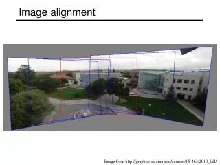
Left - Matching a widget against an image of two widgets in the plane Right – Matching a widget against an image of a foreshortened widget
3D from 2D Alignment • It is shown that the position,orientation,and scale of an object in 3D can be determined from a 2D image using three pairs of corresponding model and image points under weak perspective model • Under full perspective – up to four distinct solutions • Next: • The use of orthographic projection and a linear scale factor (weak perspective) as approximation for perspective viewing • The alignment method using explicit 3D rotation • Alignment method can be simulated using only planar operations.
Weak Perspective Projection Given a set of points In the new image:
Projection model: W.P. is good enough A point (X,Y,Z) is projected: under perspective: under weak perspective: The error is expressed by: or
Error is small when: • The measured feature is close to the optical axis or • The estimate for the depth is close to the real depth (average depth of the observed environment) Supports the intuition that for images with low depth variance and for fixed regions near the center - perspective distortions are relatively small
Alignment • Consider three model points and and three corresponding image points and ,where the model points specify 3D positions (x,y,z) and the image points specify positions in the image plane,(x,y,0) • The alignment task is to find a transformation that maps the plane defined by the three model points onto the image plane, such that each model point coincides with its corresponding image point. If no such transformation exists,then the alignment process must determine this fact • Since the viewing direction is along the z-axis,an alignment is a transformation that positions the model such that projects along the z-axis onto , and similarly for onto ,and onto
The transformation consists of translations in x and y,and rotations about three orthogonal axes. There is no translation in z (all points along the viewing axis are equivalent under orthographic projection) • First we show how to solve for the alignment assuming no change in scale,and then modify the computation to allow for a linear scale factor • First translate the model points so that one point projects along the z-axis onto corresponding image point • Using for this purpose, the model points are translated by yielding the model points and • This brings ,the projection of into the image plane into correspondence with
Now it is necessary to rotate the model about three orthogonal axes to align and with their corresponding image points.
First we align one of the model edges with its corresponding image edge by rotating the model about the z-axis • Using the edge we rotate the model by the angel between the image edge , and the projected model edge ,yielding the model points and (stage b) • To simplify the presentation, the coordinate axes are now shifted • Because ,the projection of into the image plane, lies along the x-axis,it can be brought into correspondence with by simply rotating the model about the y-axis • The amount of rotation is determined by the relative lengths of and • If the model edge is shorter than the image edge - there is no such rotation, and hence the model cannot be aligned with the image
The model points and are rotated about the y-axis by to obtain and , where (1) for (stage c) • is brought into correspondence with by rotation about the x-axis • The degree of rotation is again determined by the relative lengths of model and image edges • In the previous case the edges were parallel to the x-axis, and therefore the length was the same as the x component of the length • In this case, the edges need not be parallel to the y axis, and therefore the y component of the lengths must be used
Thus, the rotation about the x-axis is ,where (2) for (stage d) • If the model distance is shorter than the image distance,there is no transformation that aligns the model and the image • If the rotation does not actually bring into correspondence with ,then there is also no alignment • Verification: The combination of translations and rotations can now be used to map the model into the image
Scale • Linear scale factor - a sixth unknown • The final two rotations which align with , and are the only computations affected by a change in scale. • The alignment of involves movement of along the x-axis, whereas the alignment of involves movement of in both the x and y directions.
Because the movement of is a sliding along the x-axis,only the x-component, ,changes. The change is given by the rotation about the y-axis, as in (1).With a scale factor s this becomes (3) Similarly the movement of in the y direction is given by the rotation about the x-axis, as in (2).With a scale factor this becomes (4)
The movement of in the x direction is given by the rotations about both the x- and y-axis we obtain Thus with the scale factor,the x component of is (5) Now we have three equations in the three unknowns, s, and One method to solve for s is to substitute for , ,and in (5). From (3) we know that, (6)
And similarly from (4), (7) Substituting (6) and (7) into (5) and simplifying yields Expanding out the terms we obtain a quadratic in While there are generally two possible solutions, it can be shown that only one of the solutions will specify possible values of and . Having solved for the scale of an object, the final two rotations and can be computed using (1)and (2) modified to account for the scale factor s.
Issues • 3D objects: • Maintain a single 3-D model, use the recovered T and align – occlusion ** 2 • Store number of models and alignment keys representing different viewing positions • Object centered vs viewer centered • Handling DB with multiple objects
Alignment • Recognizing objects by compensating for variations Method: • The stored library of objects contains their shape and allowed transformations. • Given an image and an object model, a transformation is sought that brings the object to appear identical to the image.
Alignment (cont.) Domain: • Suitable mainly for recognition of specific object. Problems: • Complexity: recovering the transformation is time-consuming. • Indexing: library is searched serially. • Non rigidities are difficult to model.
Linear Combinations Scheme • Relates familiar views and novel views of objects in a simple way • Novel views are expressed by linear combinations of the familiar views • This is used to develop a recognition system that uses viewer-centered representations • An object is modeled by a small set of its familiar views • Recognition involves comparing the novel views to linear combinations of the model views
Weak Perspective Projection Given a set of points In the new image:
x’ y’ belong to 4D linear subspace ! For under weak perspective: In vector equation form: Consequently,
The Coefficients Theorem:The coefficients satisfy two quadratic constraints, which can be derived from three images Proof:Consider the coefficients • Since R is a rotation matrix, its row vectors are orthonormal, and therefore the following equations hold for the coefficients: • Choosing a different base to represent the object will change the constraints • The constraints depend on the transformation that separates the model views
Denote the coefficients that represent a novel view, namely and denote U the rotation matrix that separates the two model views By substituting the new coefficients we obtain new constraints:
To derive the constraints the values of and should be recovered. A third view can be used for this purpose • When a third view of the object is given, the constraints supply two linear equations in and , and, therefore, in general, their values can be recovered from the two constraints This proof suggest a simple, essentially linear structure from motion algorithm that resembles the method used in [Ullman79, Huang and Lee89]
Linear Combination For two views there exist coefficients and such that The coefficients satisfy the following two quadratic constraints: To derive these the transformation should be recovered – a third image is needed.