Download
1 / 121
1.28k likes | 1.83k Views
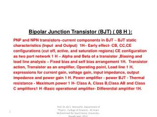
Bipolar Junction Transistor (BJT) ( 08 H ):

E N D
Bipolar Junction Transistor (BJT) ( 08 H ): • PNP and NPN transistors–current components in BJT – BJT static characteristics (Input and Output) 1H– Early effect- CB, CC,CE configurations (cut off, active, and saturation regions) CE configuration as two port network 1 H – Alpha and Beta of a transistor ,Biasing and load line analysis – Fixed bias and self bias arrangement 1H. Transistor action, Transistor as an amplifier, Operating point, Load line 1 H, expressions for current gain, voltage gain, input impedance, output impedance and power gain 1 H. Power amplifier - power BJT - Thermal resistance - Maximum power 1 H- Class A, Class B,Class AB and Class C amplifiers1 H -Basic operational amplifier- Differential amplifier 1H. Prof. Dr. Ali S. Hennache- Department of Physics - College of Sciences - Al-Imam Muhammad Ibn Saud Islamic University - Riyadh Sept. 2012.
OBJECTIVES After studying the material in this chapter, student will be able to describe and/or analyze: transistor architecture, transistors functioning as switches, transistor characteristics, base biasing of amplifier circuits, signal parameters of the amplifier circuit, the procedure for measuring input and output impedance, transistor output characteristic curves The Bipolar Transistor Prof. Dr. Ali S. Hennache- Department of Physics - College of Sciences - Al-Imam Muhammad Ibn Saud Islamic University - Riyadh Sept. 2012.
In 1947. J. Bardeen and walker Brattain were the first to invent the “transistor” by adding another junction to the p-n junction diode and Schottkty diodes which could control the flow of majority carriers and to form electronic switching circuits. During the discovery, the device was nothing more than a special kind of resistor whose value changes and thus the inventors first called it “the transformative changing variable resistor “,because of such long name, they shorted the name to “the transforming resistor” but they were still believing the name was quite long and thus they finally agreed with what is well known device in technology revolution the“Transistor” Thus, the name transistor comes from the phrase \transferring an electrical signal across aresistor". INTRODUCTION The “Transforming Resistor” Look around you, Everything you see is controlled either with computers or electronics of some sort. Your car today has more computational control systems and even energy, water, air-conditioning house are electronically controlled and all electronically controlled these days are solid state and based on the transistor so that means transistor and its derivatives are all extremely important and an absolutely basic to everyday life. In this part of the course we will find out how transistors work , how they are made and the physics behind them and what they do. Prof. Dr. Ali S. Hennache- Department of Physics - College of Sciences - Al-Imam Muhammad Ibn Saud Islamic University - Riyadh Sept. 2012.
Transistors are thus, solid state devices used for: 1- amplifying, and thus are capable of • Current gain • Voltage gain • Signal-power gain 2- controlling and 3- generating electrical signals. They are used widely in electronic equipments such as pocket calculators, radios, communication satellites and in general transistors are used in information and communication technologies (ICT). INTRODUCTION Prof. Dr. Ali S. Hennache- Department of Physics - College of Sciences - Al-Imam Muhammad Ibn Saud Islamic University - Riyadh Sept. 2012.
E E Base (n-type) Base (p-type) C C Emitter (n-type) Emitter (p-type) Collector (p-type) Collector (n-type) B B A transistor is a three-layer devicealternately doped semiconductor regions, whereas a diode has only two layers. Figure 1(a) shows how two layers of N-type material sandwich one layer of P-type material to make an NPN transistor. Figure 1(b) shows how two layers of P-type material sandwich one layer of N-type material to form a PNP transistor.Most transistors used today are NPN because this is the easiest type to make from silicon .In both cases, the layer in the center is the base, and the two outer layers are the emitter and collector. The arrow on the schematic symbol identifies the emitter and always points to the N-type material. Bipolar junction transistor fundamentals (b) (a) Figure 1: A three-layer device (Transistor),(a) shows how two layers of N-type material sandwich one layer of P-type ,(b) shows how two layers of N-type material sandwich one layer of P-type. Prof. Dr. Ali S. Hennache- Department of Physics - College of Sciences - Al-Imam Muhammad Ibn Saud Islamic University - Riyadh Sept. 2012.
Bipolar transistors, also called BJTs (Bipolar Junction Transistors), are three-terminal devices that can function as electronic switches or as signal amplifiers. In this chapter, you will learn how transistors perform both of these important functions. Figure 2. shows the schematic symbols for the two types of bipolar transistors. The schematic symbols show the three terminals of the transistor. The leg with the arrow is called the emitter (E), the collector (C) is the other slanted leg, and the middle region the base(B) is the leg connected perpendicular to the line connecting the emitter and the collector andis very thin compared to the diffusion length of minority carriers These terms refer to the internal operation of a transistor but they are not much help in understanding how a transistor is used. The Bipolar Transistor Collector Collector Base Base Figure 2. Transistor symbols NPN TYPE Emitter PNP TYPE Emitter Prof. Dr. Ali S. Hennache- Department of Physics - College of Sciences - Al-Imam Muhammad Ibn Saud Islamic University - Riyadh Sept. 2012.
The emitter (E) and is heavily doped (n-type). The collector (C) is also doped n-type. The base (B) is lightly doped with opposite type to the emitter and collector (i.e. p-type in the npn transistor). The base is physically very thin . npn BJT Structure Prof. Dr. Ali S. Hennache- Department of Physics - College of Sciences - Al-Imam Muhammad Ibn Saud Islamic University - Riyadh Sept. 2012.
NPN vs PNP • 1) NPN. If the base is at a higher voltage than the emitter, current flows from collector to emitter. • 2) NPN. Small amount of current also flows from base to emitter. • 3) NPN. Voltage at base controls amount of current flow through transistor (collector to emitter). • 4) PNP. If the base is at a lower voltage than the emitter, current flows from emitter to collector. • 5) PNP. Small amount of current also flows from emitter to base. • 6) PNP. Voltage at base controls amount of current flow through transistor (emitter to collector). • 7) The arrow to shows the direction of current flow. Prof. Dr. Ali S. Hennache- Department of Physics - College of Sciences - Al-Imam Muhammad Ibn Saud Islamic University - Riyadh Sept. 2012.
Darlington pair is two transistors connected together to give a very high current gain. In addition to standard (bipolar junction) transistors, there are (Figure 3): The Field-Effect Transistor which are usually referred to as FETs The Metal-Oxide Semiconductor Field-Effect Transistor (MOSFET) The Uni -Junction Transistor (UJT). All the three above types are beyond the scope of this chapter TYPES OF TRANSISTORs http://www.mikroe.com/old/books/keu/04.htm • Darlington pair • This is two transistors connected together so that the current amplified by the first is amplified further by the second transistor. The overall current gain is equal to the two individual gains multiplied together: • Figure. 3: Different transistors Prof. Dr. Ali S. Hennache- Department of Physics - College of Sciences - Al-Imam Muhammad Ibn Saud Islamic University - Riyadh Sept. 2012.
E Base (p-type) C Emitter (n-type) Collector (n-type) B - VCE + Current flow convention IC IE - VBE + + VBC - IB We shall treat the transistor as a current node and write according to 1st and 2nd Law of Kirchhoff the following : IE = IB + ICand VEB + VBC + VCE = 0 VCE= VEC Prof. Dr. Ali S. Hennache- Department of Physics - College of Sciences - Al-Imam Muhammad Ibn Saud Islamic University - Riyadh Sept. 2012.
E Base (n-type) C Emitter (p-type) Collector (p-type) B + VEC - Current flow convention IC IE + VEB - IB - VCB + IE = IB + ICand VEB + VBC + VCE = 0 VCE= VEC Prof. Dr. Ali S. Hennache- Department of Physics - College of Sciences - Al-Imam Muhammad Ibn Saud Islamic University - Riyadh Sept. 2012.
Most electronic devices take the signal between two input terminals and deliver from it an output signal between two output terminals. • The BJT has only three terminals so one of these is usually shared (i.e. made common) between input and output circuits. In this chapter all three methods that a transistor can be connected will be covered 1-common emitter (CE), 2-common base (CB) and 3-common collector (CC) configurations. TRANSISTOR CONFIGURATIONS The CE configuration is the one most commonly encountered since it provides both good current and voltage gain for ac signals. In the CE configuration the input is between the base and the emitter. The output is between the collector and the emitter. Prof. Dr. Ali S. Hennache- Department of Physics - College of Sciences - Al-Imam Muhammad Ibn Saud Islamic University - Riyadh Sept. 2012.
The p-n junction joining the base and emitter regions is called the base-emitter (B-E) junction. (or emitter-base) The p-n junction between the base and collector regions is called the collector-base (C-B) junction.(or base-collector) TRANSISTOR CONFIGURATIONS In normal operation for analogue (linear amplifier) circuits the emitter-base junction is forward biased and the collector-base junction is reverse biased. These ‘bias’ or ‘quiescent’ conditions are set by d.c. bias circuits. The a.c. (‘analogue’) signal to be amplified is superimposed on top of the d.c. bias voltages and currents. (Exactly as for dynamic resistance, small variations about a Q point, in our discussion of diodes.) The forward bias between the base and emitter injects electrons from the emitter into the base and holes from the base into the emitter. Prof. Dr. Ali S. Hennache- Department of Physics - College of Sciences - Al-Imam Muhammad Ibn Saud Islamic University - Riyadh Sept. 2012.
Comparison of the characteristic sizes (table below) of the 3 different transistor connections . GENERAL CONNECTION CHARACTERISTICS Prof. Dr. Ali S. Hennache- Department of Physics - College of Sciences - Al-Imam Muhammad Ibn Saud Islamic University - Riyadh Sept. 2012.
If Vin is high, T is ON, switch is closed and Vout is low. Digital “0” If Vin is low, T is OFF, switch is open and Vout is high. Digital “1” SWITCH FUNCTION Switch function occurs when high base voltage (>0.7 V)saturates the transistor and it fully conducts current in the C-E path resulting in Vout =0. or when the the base voltage is negative. Then it cuts off the current in the C-E path and Vout =Vcc. This is the means by which digital or on/off switching can be accomplished and forms the basis for all digital circuits (including computers) Prof. Dr. Ali S. Hennache- Department of Physics - College of Sciences - Al-Imam Muhammad Ibn Saud Islamic University - Riyadh Sept. 2012.
A transistor can function as an SPST (single-pole single-throw) switch, but rather than being mechanically controlled, it is controlled by an electronic signal driving the base terminal. Figure below shows a comparison between an open SPST switch and an NPN transistor. TRANSISTOR SWITCHES When the switch is open, as shown in Figure 4–8(a), there is no current flowing in the circuit and the bulb is off. When the control signal on the base terminal of the transistor turns the transistor off, as shown in Figure 4–8(b), the transistor acts like an open switch. The resistance between the collector and the emitter terminals rises infinitely high and prevents current flow in the circuit. The bulb in series with the transistor is off. Figure 4–8 Open switch equals off transistor Prof. Dr. Ali S. Hennache- Department of Physics - College of Sciences - Al-Imam Muhammad Ibn Saud Islamic University - Riyadh Sept. 2012.
Figure below shows a comparison between the SPST switch and the transistor when turned on. When the switch is closed, current flows in the circuit and lights the bulb. Likewise, when the control signal on the base terminal turns the transistor on, the resistance between the collector and emitter drops to zero, and the current flow lights the bulb. Actually, the transistor is not a perfect switch. When it is off, the resistancebetween the collector and emitter (RCE) does not go to infinity, and when it is on, the resistance between the collector and emitter (RCE) does not drop to zero. Even though the transistor is not a perfect switch, it is close enough to function well in most circuits. COMPARISON OF SPST SWITCH AND TRANSISTOR “CLOSED” switch = “ON” TRANSISTOR Prof. Dr. Ali S. Hennache- Department of Physics - College of Sciences - Al-Imam Muhammad Ibn Saud Islamic University - Riyadh Sept. 2012.
Each configuration, as you will see later, has particular characteristics that make it suitable for specific applications. An easy way to identify a specific transistor configuration is to follow three simple steps: 1- Identify the element (emitter, base, or collector) to which the input signal is applied. 2- Identify the element (emitter, base, or collector) from which the output signal is taken. 3- The remaining element is the common element, and gives the configuration its name. Therefore, by applying these three simple steps to the circuits in figure on the left , we can conclude that this circuit is more than just a basic transistor amplifier. 1st it is a common-emitter amplifier,2nd is a common base amplifier and 3rd is a common collector amplifier CONFIGURATIONS AS AMPLIFIER Prof. Dr. Ali S. Hennache- Department of Physics - College of Sciences - Al-Imam Muhammad Ibn Saud Islamic University - Riyadh Sept. 2012.
Silicon transistor (bipolar junction transistor) • high gain, bandwidth, analog amplifier • FET (field effect transistor) • high input impedance, analog amplifier • MOS FET (Metal Oxide Field Effect Transistor) • digital, fast switching (preferred in computers, microprocessors) • CMOS (Complementary Metal Oxide Semiconductor) Transistor • low power, digital switching and analog (preferred in low power implanted devices) Transistors applications Prof. Dr. Ali S. Hennache- Department of Physics - College of Sciences - Al-Imam Muhammad Ibn Saud Islamic University - Riyadh Sept. 2012.
1 = hole current lost due to recombination in base, IBR 2 = hole current collected by collector, ~ IC 1 + 2 = hole part of emitter current, IEP 5 = electrons injected across forward biased E-B junction, (– IBE); same as electron part of emitter current, – IEN 4 = electron supplied by base contact for recombination with holes lost, – IBR (= 1) 3 = thermally generated e& h making up reverse saturation current of reverse biased C-B junction. (generally neglected) Current components Prof. Dr. Ali S. Hennache- Department of Physics - College of Sciences - Al-Imam Muhammad Ibn Saud Islamic University - Riyadh Sept. 2012.
There are hundreds of transistors on the market. The differences in these transistors can be found by examining the electrical characteristics listed on the data sheets. The three most important characteristics to know are: 1- the maximum collector current (IC), 2- maximum power dissipation (PD), and 3- small signal beta (β). TRANSISTOR CHARACTERISTICS AND DATA SHEETS Maximum collector current (IC) is the maximum continuous current that can flow in the collector leg of the transistor without damage to the transistor. Bipolar transistors are available with maximum collector current ratings from 50 mA to 50 A. Maximum power dissipation (PD) is the maximum power the transistor can dissipate without being damaged. An approximation of the power being dissipated by a transistor can be calculated by multiplying the voltage across the transistor from collector to emitter (VCE) times the collector current (IC). Bipolar transistors are available with maximum power dissipation ratings from 0.2 W to 250 W. Prof. Dr. Ali S. Hennache- Department of Physics - College of Sciences - Al-Imam Muhammad Ibn Saud Islamic University - Riyadh Sept. 2012.
DC beta (β) or (hFE) is the DC current gain of the transistor in the common-emitter configuration. In most applications, the small signal beta and the DC beta are interchangeable. In this text, we will assume they are interchangeable unless otherwise noted. The formula for DC beta is β = IC/IB. Transistors are available with beta ratings from 10 to 1000. BETA (hfe) OF THE TRANSISTOR Maximum base current (IB) is the maximum current that can flow in the base leg of the transistor without damage to the transistor. Collector to base breakdown voltage (VCBO) is the maximum reverse-biased voltage that can be applied across the collector to base junction. Bipolar transistors are available with collector to base breakdown voltage ratings from 20 V to 1500 V. Prof. Dr. Ali S. Hennache- Department of Physics - College of Sciences - Al-Imam Muhammad Ibn Saud Islamic University - Riyadh Sept. 2012.
The ratio of how the emitter current divides into base and collector current is a function of the particular transistor being used. Typically only about 1% of the emitter current will exit the base, and 99% will exit the collector. The ratio of collector current to base current is a parameter of the individual transistor and is called beta (β). Beta can be stated mathematically as β = IC/IB. Beta is sometimes referred to as hFE, which stands forforwardcurrent gain in the common emitter configuration. Beta is the current gain of the transistor where IC is output current and IB is input current (beta has no units, since it is a ratio of two currents). The important thing to remember about beta is that it is a fixed ratio between collector current and base current. Therefore, a small change in base current will cause a large change in collector current. The base current is the control current. BETA OF THE TRANSISTOR IE = IB + ICTransistor current divider β = IC / IB Transistor current gain (beta) Prof. Dr. Ali S. Hennache- Department of Physics - College of Sciences - Al-Imam Muhammad Ibn Saud Islamic University - Riyadh Sept. 2012.
Neglect the reverse leakage (electron) current of C-B junction Emitter efficiency: Performance parameters (pnp) Fraction of emitter current carried by holes. close to 1. Base transport factor: Fraction of holes collected by the collector. T close to 1. Common base dc current gain: Note that is less than 1.0 but close to 1.0 (e.g. = 0.99) Prof. Dr. Ali S. Hennache- Department of Physics - College of Sciences - Al-Imam Muhammad Ibn Saud Islamic University - Riyadh Sept. 2012.
Common emitter dc current gain, dc: Performance parameters (pnp) Note that is large (e.g. = 100) For NPN transistor, similar analysis can be carried out. However, the emitter current is mainly carried by electrons. Prof. Dr. Ali S. Hennache- Department of Physics - College of Sciences - Al-Imam Muhammad Ibn Saud Islamic University - Riyadh Sept. 2012.
EXAMPLE 01 A transistor is connected as shown in Figure 1. It has a base current of 8 μA and a collector current of 1.2 mA. What is the emitter current and the beta of the transistor? Step 1 Calculate emitter current. IE = IB + IC IE = 8 μA + 1.2 mA IE = 1208 μA Step 2 Calculate beta. β = IC/IB β = 2400 μA / 20 μA β = 120 EXAMPLES Figure 1 • EXAMPLE 02 A transistor is connected as shown in Figure 1. It has an emitter current of 2.42 mA and a collector current of 2.4 mA. What is the base current and beta of the transistor? Step 2 Calculate beta. β = IC/IB β = 1200 mA/8 mA β = 150 Step 1 Calculate base current. IE = IB + IC IB = IE – IC IB = 2.42 mA – 2.40 mA = 0.02 mA or 20 μA Prof. Dr. Ali S. Hennache- Department of Physics - College of Sciences - Al-Imam Muhammad Ibn Saud Islamic University - Riyadh Sept. 2012.
EXAMPLE 03 A transistor is connected as in Figure 1 and has a base current of 16 μA and a beta of 80. What is the collector current and emitter current of the transistor? Step 1 Calculate the collector current. β = IC/IB EXAMPLES IC = β × IB IC= 80 × 16μA IC= 1280 μA or 1.28 mA Step 2 Calculate the emitter current. IE = IB + IC IE = 16 μA + 1280 μA = 1296 μA or 1.296 mA Prof. Dr. Ali S. Hennache- Department of Physics - College of Sciences - Al-Imam Muhammad Ibn Saud Islamic University - Riyadh Sept. 2012.
EXAMPLE 04 Design a circuit to control the on/off conditions of a 50 Ω load connected to 30 V. The control signal is a voltage switch between 0 V and 4 V. The load will be on when the control voltage is 4 V and off when the control voltage is 0 V. The transistor used in the circuit will have a beta of 50. examples • Step 1 • Draw a diagram of the switching circuit. (Figure 2 shows a diagram of the circuit.) Prof. Dr. Ali S. Hennache- Department of Physics - College of Sciences - Al-Imam Muhammad Ibn Saud Islamic University - Riyadh Sept. 2012.
Step 2 Calculate the collector current when the load is in the on state. The supply voltage is divided by the load resistance. The saturation voltage (0.2 V) of the transistor could be subtracted from the supply voltage, but it is not significant in this case. IC = IL = 30 V/50 Ω = 600mA Step 3 Calculate the base current needed. IB = IC/β = 600 mA/50 = 12 mA Step 4 Calculate the value of VRB. VRB = Vcontrol – VBE = 4 V – 0.7 V = 3.3 V Step 5 Calculate the value of Rb. Rb = VRB/IB = 3.3 V/12 mA = 275 Ω Examples Prof. Dr. Ali S. Hennache- Department of Physics - College of Sciences - Al-Imam Muhammad Ibn Saud Islamic University - Riyadh Sept. 2012.
Figure 4–10 shows a transistor switching circuit designed to control the on/off condition of a 12 V bulb.When the control signal equals 5 V, the bulb is on, and when the control signal equals 0 V, the bulb is off. The current flowing through the bulb is the collector current. The collector current is zero when the bulb is off and is limited by the bulb resistance when the bulb is on. Example 4.4 shows how to design the switching circuitry. Electronics “ Phys. 324 ” • EXAMPLE 4.4 Step 1. Calculate the collector current when the bulb is in the on state. The supply voltage is divided by the resistance of the load (bulb). IC = IL = VCC/RL = 12 V/10 Ω = 1.2 A Step 2. Using beta, calculate the needed base current. IB = IC/β = 1.2 A/100 = 12 mA Step 3. Calculate the value of VRB. VRB = Vcontrol – VBE = 5 V – 0.7 V = 4.3 V Step 4. Calculate the value of Rb. Rb = VRB/IB = 4.3 V/12 mA = 358 Ω (Use the next lower standard value, 330 Ω.) Step 5. Draw the switching circuit. (The switching circuit is shown in Figure 4–10.) Design the transistor switching circuit shown in Figure 4–10. Prof. Dr. Ali S. Hennache- Department of Physics - College of Sciences - Al-Imam Muhammad Ibn Saud Islamic University - Riyadh Sept. 2012.
GAIN AND AMPLIFICATION Transistor amplifiers are circuits that provide signal gain. Gain is an important concept in electronics. Let us take a moment to make sure we have a common understanding of the word. Gain is the ratio of output to input. The general formula is Gain = Output/Input. Gain has no units because the output and the input must be in the same units, and the units cancel. THE TRANSISTOR AMPLIFIER Figure below shows the symbol used for an amplifier. An amplifier is an electronic circuit used to obtain gain. In the figure , the amplifier has an input of 0.6 Vp-p and an output of 6 Vp-p. By using the gain formula, we can calculate the voltage gain to be: (6 Vp-p/0.6 Vp-p = 10). The word voltage preceding gain indicates that the gain ratio is comprised of the output voltage and the input voltage. It is also possible to have current and power gains. Prof. Dr. Ali S. Hennache- Department of Physics - College of Sciences - Al-Imam Muhammad Ibn Saud Islamic University - Riyadh Sept. 2012.
The general formula for the Gain (G) or Amplification (A) is: GV (AV) = Output / Input Expressions for gains Voltage Gain : GV (AV) = VOutput / VInput Current Gain : GI (AI) = IOutput / IInput Power Gain : Gp (Ap) = GV (AV) . GI (AI) Prof. Dr. Ali S. Hennache- Department of Physics - College of Sciences - Al-Imam Muhammad Ibn Saud Islamic University - Riyadh Sept. 2012.
Darlington pair As we already said that this is two transistors connected together so that the current amplified by the first is amplified further by the second transistor. The overall current gain is equal to the two individual gains multiplied together: Darlington pair current gain, hFE = hFE1 × hFE2 (hFE1 and hFE2 are the gains of the individual transistors) This gives the Darlington pair a very high current gain, such as 10000, so that only a tiny base current is required to make the pair switch on. A Darlington pair behaves like a single transistor with a very high current gain.It has three leads (B, Cand E) which are equivalent to the leads of a standard individual transistor. To turn on there must be 0.7V across both the base-emitter junctions which are connected in series inside the Darlington pair, therefore it requires 1.4V to turn on. Electronics “ Phys. 324 ” Prof. Dr. Ali S. Hennache- Department of Physics - College of Sciences - Al-Imam Muhammad Ibn Saud Islamic University - Riyadh Sept. 2012.
A graph showing collector current (IC) versuscollector/emitter voltage (VCE) with base current (IB) held constant is called an output characteristic curve. Figure (a) below shows an experimental circuit used to obtain the needed data to draw an output characteristic curve. Figure (b) shows the output characteristic curve obtained by holding the base current constant at 5 μΑ and monitoring the collector current as the collector/emitter voltage is varied from 0 V to 20 V. TRANSISTOR OUTPUT CHARACTERISTIC CURVES Family of output characteristic curves Circuit for developing characteristic curves If the base current is adjusted to a second value and the process is repeated, data can be obtained for a second curve. This process can be repeated several times, and a family of output characteristic curves can be obtained as shown in Figure on the right. Prof. Dr. Ali S. Hennache- Department of Physics - College of Sciences - Al-Imam Muhammad Ibn Saud Islamic University - Riyadh Sept. 2012.
Inside transistor The following drawing shows how the electrons and holes flow within the transistor This is generally what happens inside a transistor when voltage is applied. The purpose of this theory is to explain how can someone use the transistor to design an amplifier or a switch. In any transistor scheme the symbol VEE is for the emitter supply, VCC for the collector supply andVBBfor the base supply. Prof. Dr. Ali S. Hennache- Department of Physics - College of Sciences - Al-Imam Muhammad Ibn Saud Islamic University - Riyadh Sept. 2012.
The hybrid parameters [h] The hybrid parameters are values that characterize the operation of a transistor, such as the amplification factor, the resistance and others. They are used to calculate and properly use the transistor in a circuit. Most of the the hybrid parameter values are given in the datasheet by the manufacturer. Hybrid parameters The hybrid parameters for Common Emitter (CE) connection Here is the first set of hybrid parameters for a transistor connected with Common Emitter. hie - input impedanceThe first hybrid parameter that we will see is the hie. This parameter is defined by the result of the division of the VBE with the IB: hie = VBE / IB This parameters defines the input resistance of a transistor, when the output is short-circuited (VCE=0). Prof. Dr. Ali S. Hennache- Department of Physics - College of Sciences - Al-Imam Muhammad Ibn Saud Islamic University - Riyadh Sept. 2012.
hfe - Current GainThis is the most important parameter and is extensively used when calculating a transistor amplifier. This is actually the only parameter you need to know to begin designing amplifiers. The equation for this parameter is the following: hfe = IC / IB When we have the output of the transistor short-circuited (VCE=0), hfe defines the current gain of the transistor in common emitter (CE) connection. Using this parameter we can calculate the output current (IC) from the input current (IB): IC = IB x hfe This explains why this parameter is so useful. A typical BJT transistor has typical current amplification from 30 to 800, while a Darlington pair transistor can have an amplification factor of 10.000 or more. Another symbol for the hfe is the Greek letter β (Beta). Hybrid parameters Prof. Dr. Ali S. Hennache- Department of Physics - College of Sciences - Al-Imam Muhammad Ibn Saud Islamic University - Riyadh Sept. 2012.
hre - Dynamic transfer ratio reverse voltageThis parameter is calculated with this equation: hre = VBE / VCE If the input of the transistor is open (IB=0) then this parameter gives the voltage gain when the transistor is connected with common emitter (CE). hoe - Output ConductivityThis parameter is defined with the input open (IB=0) and the transistor connected in common emitter (CE) connection. The equation is: hoe = IC / VCE With the above conditions, this parameter defines the conductivity of the output. So, the impedance of the output can be defined as follows: Hybrid parameters ro = 1 / hoe = VCE / IC Prof. Dr. Ali S. Hennache- Department of Physics - College of Sciences - Al-Imam Muhammad Ibn Saud Islamic University - Riyadh Sept. 2012.
One of the most important characteristics is the Common Emitter output characteristic or IC to VCE characteristic and looks like as below: Output characteristic, Load Lines and Quiescence point The DC Load Line This is the IC to VCE characteristic of a BC547 transistor. The horizontal axis (x) has the VCE voltage in volts, and the vertical axis has the IC current, usually in milliamperes. Between them, there are several different curves. Each one of these lines corresponds to a different base current, usually measured in microamperes. The IC to VCE characteristic of a transistor Prof. Dr. Ali S. Hennache- Department of Physics - College of Sciences - Al-Imam Muhammad Ibn Saud Islamic University - Riyadh Sept. 2012.
The DC Load Line is a line (red line ) on these characteristics, which eventually determines all the points that the transistor will operate at. In other words, the operation point (usually called Q from the word "Quiescence") will be somewhere on the DC load line. To draw this load line, the collector current and the collector-emitter voltage needed to be known. For example for the characteristics below the load line drawn with red color is for IC=40mA and VCE=12V. Dc load line (operation point) • How to draw the load line Before one can draw the load line, we must first discuss and explain the 4 basic regions of the output characteristic or IC to VCE 1- the saturation area, 2- the cut-off area, 3- the linear area and 4- the breakdown point. Prof. Dr. Ali S. Hennache- Department of Physics - College of Sciences - Al-Imam Muhammad Ibn Saud Islamic University - Riyadh Sept. 2012.
Region 1: The Saturation Area The saturation area is the area where the load line intersects with the saturation point of the characteristics. In the following curves , the saturation area is marked with a red transparent filter. SATURATION AREA Prof. Dr. Ali S. Hennache- Department of Physics - College of Sciences - Al-Imam Muhammad Ibn Saud Islamic University - Riyadh Sept. 2012.
Region 2: The Cut-Off area The cut-off area is the area in which the collector current becomes zero. In the following curves , the cut-off area is marked with a yellow transparent filter. Cut- off area Prof. Dr. Ali S. Hennache- Department of Physics - College of Sciences - Al-Imam Muhammad Ibn Saud Islamic University - Riyadh Sept. 2012.
Region 3: The Linear Area The linear area is the area between the cutoff and the saturation area of the transistor, as shown bellow with a green mask. Linear area Prof. Dr. Ali S. Hennache- Department of Physics - College of Sciences - Al-Imam Muhammad Ibn Saud Islamic University - Riyadh Sept. 2012.
Region 4: The Breakdown Point The breakdown point is the point above which the collector current increases rapidlyand the transistor is destroyed. This area is marked with a purple mask in the following drawing. Breakdown point Prof. Dr. Ali S. Hennache- Department of Physics - College of Sciences - Al-Imam Muhammad Ibn Saud Islamic University - Riyadh Sept. 2012.
Q.1- What are the three transistor configurations? Q.2- Which transistor configuration provides a phase reversal between the input and output signals? Q.3- What is the input current in the common-emitter circuit? Q.4- What is the current gain in a common-base circuit called? Q.5- Which transistor configuration has a current gain of less than 1? Q.6- What is the output current in the common-collector circuit? Q.7- Which transistor configuration has the highest input resistance? Q.8- What is the formula for GAMMA Test Prof. Dr. Ali S. Hennache- Department of Physics - College of Sciences - Al-Imam Muhammad Ibn Saud Islamic University - Riyadh Sept. 2012.
Amplifier Parameters Any amplifier is said to have certain parameters. These are the particular properties that make the amplifier perform in a certain way, and so make it suitable for a given task. Typical amplifier parameters are described below. Gain The gain of an amplifier is a measure of the "Amplification" of an amplifier, i.e. how much it increases the amplitude of a signal. More precisely it is the ratio of the output signal amplitude to the input signal amplitude, and is given the symbol "A". It can be calculated for voltage (Av), current (Ai) or power (Ap). AMPLIFIER PARAMETERS • Amplification • The Voltage Amplification (Av) or Gain of a voltage amplifier is given by: Voltage gain Av = Amplitude of output voltage ÷ Amplitude of input voltage. Prof. Dr. Ali S. Hennache- Department of Physics - College of Sciences - Al-Imam Muhammad Ibn Saud Islamic University - Riyadh Sept. 2012.
Current gain Ai = Amplitude of output current ÷ Amplitude of input current. AMPLIFIER PARAMETERS • Power gain Ap = Signal power out ÷ Signal power in. The gain of an amplifier is governed, not only by the components (transistors etc.) used, but also by the way they are interconnected within the amplifier circuit. Prof. Dr. Ali S. Hennache- Department of Physics - College of Sciences - Al-Imam Muhammad Ibn Saud Islamic University - Riyadh Sept. 2012.
The dBs can be used to indicate the gain of amplifiers • Converting a power gain ratio to dBs is calculated by multiplying the log of the ratio by 10: AMPLIFIER PARAMETERS • When voltage gain(Av) or current gain (Ai) is plotted against frequency the −3dB points are where the gain falls to 0.707 of the maximum (mid band) gain. Prof. Dr. Ali S. Hennache- Department of Physics - College of Sciences - Al-Imam Muhammad Ibn Saud Islamic University - Riyadh Sept. 2012.
There are four classes of operation for an amplifier(Figure 1). These are: A, AB, B and C (figure 1 (A), 1(B) (1C) and (1D) respectively) .Each class of operation has certain uses and characteristics. AMPLIFIERS CLASSES The class of operation of an amplifier is determined by the amount of time (in relation to the input signal) that current flows in the output circuit The selection of the "best" class of operation is determined by the use of the amplifying circuit. Figure 1: A comparison of output signals for the different amplifier classes of operation Prof. Dr. Ali S. Hennache- Department of Physics - College of Sciences - Al-Imam Muhammad Ibn Saud Islamic University - Riyadh Sept. 2012.
CLASS A The output is a replica of the input. Figure 2 is an example of a class A amplifier. Although the output from this amplifier is 180 degrees out of phase with the input, the output current still flows for the complete duration of the input and thus, amplifier current flows for 100% of the input signal. The class A operated amplifier is used as an audio- and radio-frequency amplifier in radio, radar, and sound systems, just to mention a few examples. CLASS A AMPLIFIER The class A amplifier has the characteristics of good FIDELITY( the output signal is just like the input signal in all respects except amplitude) and low EFFICIENCY. • Class A - 100% of the input signal is used (conduction angle a = 360° or 2π) • Figure 2: A simple class A transistor amplifier. Prof. Dr. Ali S. Hennache- Department of Physics - College of Sciences - Al-Imam Muhammad Ibn Saud Islamic University - Riyadh Sept. 2012.