View Transformation
660 likes | 923 Views
View Transformation. CSC 830 Note 3. Course note credit to Prof. Seth Teller, MIT. View Transformation. Transform (i.e., express) geometry into coordinates that are well-suited to (simple) clipping and projection hardware. Positioning Synthetic Camera.

View Transformation
E N D
Presentation Transcript
View Transformation CSC 830 Note 3 Course note credit to Prof. Seth Teller, MIT
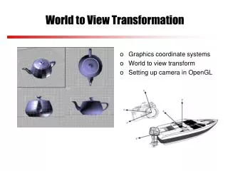
View Transformation Transform (i.e., express) geometry into coordinates that are well-suited to (simple) clipping and projection hardware
Positioning Synthetic Camera What are our “degrees of freedom” in camera positioning? To achieve effective visual simulation, we want: 1) the eye point to be in proximity of modeled scene 2) the view to be directed toward region of interest, and 3) the image plane to have a reasonable “twist”
Eye Coordinates Eyepoint at origin u axis toward “right” of image plane v axis toward “top” of image plane view direction along negative n axis
Transformation to Eye Coordinates Our task: construct the transformation M that re-expresses world coordinates in the viewer frame
Machinery: Changing Orthobases Suppose you are given an orthobasis u, v, n What is the action of the matrix M with rows u, v, and n as below?
Applying M to u, v, n Two equally valid interpretations, depending on reference frame: 1: Think of uvn basis as a rigid object in a fixed world space Then M “rotates” uvn basis into xyz basis 2: Think of a fixed axis triad, with “labels” from xyz space Then M “reexpresses” an xyz point p in uvn coords! It is this second interpretation that we use today to “relabel” world-space geometry with eye space coordinates
Positioning Synthetic Camera Given eyepoint e, basis ˆu, ˆv, ˆn Deduce M that expresses world in eye coordinates: Overlay origins, then change bases:
Positioning Synthetic Camera Check: does M re-express world geometry in eye coordinates?
Positioning Synthetic Camera Camera specification must include: World-space eye position e World-space “lookat direction” -n Are e and -n enough to determine the camera DOFs (degrees of freedom)?
Positioning Synthetic Camera Are e and -n enough to determine the camera DOFs? No. Note that we were not given u and v! (Why not simply require the user to specify them?) We must also determine u and v, i.e., camera “twist” about n. Typically done by specification of a world-space “up vector” provided by user interface, e.g., using gluLookat(e, c, up) “Twist” constraint: Align v with world up vector (How?)
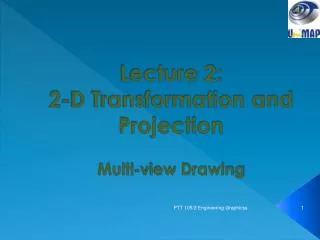
What is Projection? Any operation that reduces dimension (e.g., 3D to 2D) Orthographic Projection Perspective Projection
World Image F W Image I F World Orthographic Projection • focal point at infinity • rays are parallel and orthogonal to the image plane
Simple Perspective Camera • camera looks along z-axis • focal point is the origin • image plane is parallel to xy-plane at distance d • d is call focal length
Y [Y, Z] [(d/Z)Y, d] Z [0, 0] [0, d] Similar Triangles • Similar situation with x-coordinate • Similar Triangles: point [x,y,z] projects to [(d/z)x, (d/z)y, d]
é ù é ù d 0 0 0 x ê ú ê ú é ù 0 d 0 0 y d d ê ú ê ú [ ] = Þ dx dy dz z x y d ê ú ê ú ê ú ë û 0 0 d 0 z z z ê ú ê ú ê ú ê ú ë 0 0 1 0 û ë 1 û Divide by 4th coordinate (the “w” coordinate) Projection Matrix • Projection using homogeneous coordinates: • transform [x, y, z] to [(d/z)x, (d/z)y, d] • 2-D image point: • discard third coordinate • apply viewport transformation to obtain physical pixel coordinates
Perspective Projection z = 0 not allowed (what happens to points on plane z = 0?) Operation well-defined for all other points
Perspective Projection Matrix formulation using “homogeneous 4-vectors”: Finally, recover projected point using homogenous convention: Divide by 4th element to convert 4-vector to 3-vector:
Are we ready to rasterize? Not yet. • It is difficult to do clipping directly in the viewing frustum
Perspective Projection Suppose we have transformed from World to Eye to Canonical coordinates How do we project onto “image plane”? Simply ignore z coordinate!
Qualitative Features of Perspective Projection Equal-sized objects at different depths project to different sizes! Perspective projection does not preserve shape of planar figures!
Families of parallel lines have “vanishing points” projection of point at infinity in direction of lines
OpenGL • OpenGL is a low-level graphics API • Window system independent • No facility for window events/user input • Can use additionally libraries (eg. GLUT) • Vertex driven • Primitives assembled from vertices • ***OpenGL is a state machine***
OpenGL Commands or display list per vertex operations & primitive assembly per pixel operations Frame Buffer Rasterization
Clearing the Buffers Clears the buffers using the specified values glClearColor(GLclampf red, GLclampf green, GLclampf blue, GLclampf alpha) glClear(GLbitfield mask) Masks: GL_COLOR_BUFFER_BIT, GL_DEPTH_BUFFER_BIT, GL_ACCUM_BUFFER_BIT, GL_STENCIL_BUFFER_BIT
Drawing Primitives Begin/End drawing a primitive glBegin(GLenum mode) glEnd() Modes: GL_POINTS, GL_LINES, GL_TRIANGLES, GL_TRIANGLE_STRIP, GL_QUADS, GL_POLYGON
Drawing Primitives Draw a vertex of a primitive glVertex3f(GLfloat x, GLfloat y, GLfloat z) Variants: glVertex3fv(const GLfloat *v) 2d,3d,4d, shorts, ints, floats, doubles The vertex is drawn according to the current state
Elements of Current State • Current: • Color • Normal • Texture coordinates • Drawing mode • Matrix mode • Matrix on: • Modelview stack • Perspective stack • Texture stack
Drawing Example Draw a simple square: glBegin(GL_POLYGON); glVertex3f(-0.5, 0.5,0.5); glVertex3f( 0.5, 0.5,0.5); glVertex3f( 0.5,-0.5,0.5); glVertex3f(-0.5,-0.5,0.5); glEnd();
Changing the Current Color Set the current color: glColor3f(GLfloat red, GLfloat green, GLfloat blue) Variants: glColor4f(red, green, blue, alpha) bytes, unsigned bytes, shorts, ints, floats, doubles
Drawing Example Adding color: glBegin(GL_POLYGON); glColor3f(1,0,0); glVertex3f(-0.5, 0.5,0.5); glVertex3f( 0.5, 0.5,0.5); glVertex3f( 0.5,-0.5,0.5); glVertex3f(-0.5,-0.5,0.5); glEnd();
Changing the Current Normal Set the current normal: glNormal3f(GLfloat nx, GLfloat ny, GLfloat nz) Variants: glNormal3fv(const GLfloat *v) bytes, shorts, ints, floats, doubles
Drawing Example Adding normals: glBegin(GL_POLYGON); glColor3f(1,0,0); glNormal3f(0,0,1); glVertex3f(-0.5, 0.5,0.5); glVertex3f( 0.5, 0.5,0.5); glVertex3f( 0.5,-0.5,0.5); glVertex3f(-0.5,-0.5,0.5); glEnd();
Transformation Pipeline Stages of vertex transformations: Modelview Matrix Projection Matrix Viewport Mapping Object coords Camera coords Normalized coords Window coords
Transformation Pipeline • Matrices are set up on stacks • Matrix commands are post-multiplied onto the • current matrix the last command issued is the first transformation applied to the object • Can save/restore the current matrix
Transformation Pipeline Save/Restore the current matrix: glPushMatrix() glPopMatrix() Change the current matrix stack: glMatrixMode(GLenum mode) GL_MODELVIEW, GL_PROJECTION, GL_TEXTURE
Transformation Pipeline Translate: glTranslatef(GLfloat x, GLfloat y, GLfloat z) Scale: glScalef(GLfloat x, GLfloat y, GLfloat z)
Transformation Pipeline Rotate: glRotatef(GLfloat angle, GLfloat x, GLfloat y, GLfloat z) is given in degrees angle is the unit rotation axis X,y,z
Transformation Pipeline Hierarchical Modelling: glTranslatef(waistx,waisty,waistz); glPushMatrix(); glRotatef(ra,rx,ry,rz); // draw right arm glPopMatrix(); glPushMatrix(); glRotatef(la,lx,ly,lz); // draw left arm glPopMatrix();
Drawing Example Adding transformations: glMatrixMode(GL_MODELVIEW); glBegin(GL_POLYGON); glTranslatef(0,0,0); glRotatef(0,0,1,0); glScalef(1,1,1); glColor3f(1,0,0); glNormal3f(0,0,1); glVertex3f(-0.5, 0.5,0.5); glVertex3f( 0.5, 0.5,0.5); glVertex3f( 0.5,-0.5,0.5); glVertex3f(-0.5,-0.5,0.5); glEnd();
Cameras Perspective Camera glFrustum(GLdouble left, GLdouble right, GLdouble bottom, GLdouble top, GLdouble near, GLdouble far) Orthographic Camera glOrtho(GLdouble left, GLdouble right, GLdouble bottom, GLdouble top, GLdouble near, GLdouble far)
Shading Setting the Shading Model glShadeModel(GLenum mode) Modes: GL_FLAT - FLAT shading GL_SMOOTH - GOURAUD shading