World to View Transformation
300 likes | 752 Views
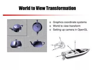
Graphics coordinate systems World to view transform Setting up camera in OpenGL. World to View Transformation. 3D Graphics Pipeline. Creating objects/scene 3D modeling and/or transformation Determining how objects/scene can be viewed Specification of camera view volume

World to View Transformation
E N D
Presentation Transcript
Graphics coordinate systems World to view transform Setting up camera in OpenGL World to View Transformation
3D Graphics Pipeline • Creating objects/scene • 3D modeling and/or transformation • Determining how objects/scene can be viewed • Specification of camera view volume • Transformation of objects to camera coordinate system • Clipping against view volume to determine visible objects • Projection of visible objects to obtain a 2D image • Determining which pixels should be filled • Rasterization from vectors/polygons to pixels • Determining color/texture/lighting at each pixel • Texture mapping and lighting models • Hidden surface removal
Graphics Coordinate Systems • 3D graphics employs a sequence of coordinate systems • The geometry of objects is expressed in local/object coordinate systems, e.g., a cube is easiest to define with faces parallel to the coordinate axes • Objects are then transformed from local to world coordinate system (world space) to create the scene • Objects are transformed from world to view coordinate system (view space) to generate 2D images, analogous to taking a photo with a camera (today’s lecture) • In OpenGL, objects are also transformed from view to canonical coordinate system (canonical space) to make projection easier
What Does Transforming to Another Space Mean? • Any point in a 3D space can be described as the sum of three basis vectors (perpendicular to each other) in a coordinate system, multiplied by some scalar coefficient, e.g., ( x, y, z )=( 1, 0, 0 ) * x + ( 0, 1, 0 ) * y + ( 0, 0, 1 ) * z • A point described in different spaces: (4,2) (0.8,0.9)
World to View Transformation • This can be done by aligning the view coordinate system with world coordinate system, e.g., view reference point is transformed to world origin, and U, V, N are aligned with X, Y, Z directions through rotations • translate camera to center • rotate around X to bring N into the X-Z plane • rotate around Y to align N with Z • rotate around Z to align U with X (V with Y) V y y y y N U V (x0, y0, z0) U U V N V x x x x N U N z z z z
Is there an Easier Way to Align World with View? • What we need is to align camera coordinates U, V and N with world coordinate X, Y and Z • This means: • U should be aligned with (1,0,0) (which is X) • V should be aligned with (0,1,0) (which is Y) • N should be aligned with (0,0,1) (which is Z) V y N U (x0, y0, z0) (0,1,0) (1,0,0) x (0,0,1) z
Is there an Easier Way to Align World with View? • This means we want to find a rotation matrix R, such that: • Each green box contains a set of 3 equations
Is there an Easier Way to Align World with View? • Solving the 9 equations we have R (you do not need to know how to solve the equations)
If coordinates of a point expressed in world space is P then coordinates of the point expressed in view space is Q = RT P If coordinates of a point expressed in view space is Q then coordinates of the point expressed in world space is T-1R-1 Q World to View Transformation
World to View Exercise • Suppose a right-handed viewing coordinate system is set up with the viewpoint at A(1,0,1), looking towards B(1,0,0), both A and B are points in the world coordinate system, and with the y axis as the 'up' vector. P is also a point in world coordinate system. • Derive an expression that gives P’s coordinates in the viewing coordinate system.
World to View Exercise • First translate the camera center to the origin • Translation matrix: Translate
World to View Exercise • Thenrotate to align the axes: As u = (-1, 0, 0), put them in v = (0, 1, 0), n = (0, 0, -1) Rotate using R
So P’s viewing coordinates Q, can be obtained by: Q = RT P World to View Execise
Camera (virtual) in Graphics • Images are formed in camera coordinate system and are dependant on camera position and orientation in the 3D space, as well as camera properties • So in graphics we define a view coordinate system (or a virtual camera), which involves specifying • camera position in world coordinate system • camera viewing direction • camera up direction
Setting up Camera in OpenGL • Suppose u, v, n arethe camera/view coordinate axes, • n, the given view plane normal, gives the camera viewing direction • v, the up vector. If v is not perpendicular to n, then can use it to find a perpendicular vector to n • u, the 3rd camera coordinate axis, can be constructed by right handed system: uv=n • P0, the view reference point (or lookatpoint in OpenGL), can be chosen anywhere along the camera direction in the world coordinate system v u y P0 n x z
Cross Product Reminder • A x B ( “A cross B”) is the normal vector to both A and B, i.e. the one that is at right angles to A and B y B = (x2,y2, z2) n = (nx, ny, nz) θ o x z A = (x1,y1, z1) n = ( y1z2-z1y2, z1x2-x1z2, x1y2-y1x2)
Setting Up Camera in OpenGL • Consider a camera with eye = (4,4,4) ; look = (0,1,0); up = (0,1,0) • Find u, v, and n of the camera coordinate system y (4,4,4) v n (0,1,0) y (4,4,4) x n (0,1,0) z u x n = look - eye = (0, 1, 0) - (4, 4, 4) = (-4,-3,-4) z
u =up X n = (0,1,0) x (-4,-3,-4)= (-4,0,4); Setting Up Camera in OpenGL y u n x z
v =n X u = (-4, -3, -4) X (-4, 0, 4) = (-12,-32,12); Setting Up Camera in OpenGL v y u n x z
x y -z Setting up Camera in OpenGL • In OpenGL (right handed), the default camera position is at the coordinate origin of the world space, looking along the negative z direction, and the view plane is perpendicular to the viewing direction • GL_MODELVIEW matrix is the product of two matrices: • One matrix M embodies all the modelling transformations applied to points • The other matrixVtransforms world to camera coordinates eye
x y -z Setting up Camera in OpenGL • When gluLookAt (ex,ey,ez,rx,ry,rz,ux,uy,uz) is called, OpenGL builds the Vmatrix and post-multiplies the current matrix by it, where • (ex,ey,ez) gives the eye position • (rx,ry,rz) gives the reference or lookat point • (ux,uy,uz) gives the up vector up eye lookat