Download
1 / 32
370 likes | 797 Views
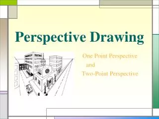
Lecture 2: 2-D Transformation and Projection Multi-view Drawing. Outline. Projection Theory Multi-view Projection Principle views & View placement Projection angle Detail drawing: 1view, 2 view, 3 view drawing Creating multi-view drawing View Selection. Projection Theory.

E N D
Lecture 2:2-D Transformation and ProjectionMulti-view Drawing PTT 105/3 Engineering Graphicss
Outline • Projection Theory • Multi-view Projection • Principle views & View placement • Projection angle • Detail drawing: 1view, 2 view, 3 view drawing • Creating multi-view drawing • View Selection PTT 105/3 Engineering Graphicss
Projection Theory • Engineering and technical graphics are depend on projection methods. • Two methods commonly used: • Parallel: object positioned at infinity& viewed from multiple points on an imaginary line, parallel to the object. • Perspective: object positioned atfinite distance & viewed from a single point. PTT 105/3 Engineering Graphicss
Projection theory comprises of principles used to graphically represent 3D objects on 2D media based on 2 variables: • Line of Sight (LOS): an imaginary ray of light between an observer’s eye and an object. • Parallel- all LOS are parallel • Perspective- all LOS start at a point. • Plane of projection: an imaginary flat plane where the image created by LOS is projected. PTT 105/3 Engineering Graphicss
Orthographic Projection • A parallel projection technique • The projection plane is placed between observer and object. • The projection plane is also perpendicular to the parallel line of sight. PTT 105/3 Engineering Graphicss
Multi-view projection • Multi-view projection is an orthographic projection for which the object is behind the plane of projection. PTT 105/3 Engineering Graphicss
Multi-view drawings i. Employ multi-view projection technique ii. Generally 3 views of an object are drawn iii. Each view is a 2D flat image PTT 105/3 Engineering Graphicss
Example: Multi-view Projection PTT 105/3 Engineering Graphicss
Multi-view Lines PTT 105/3 Engineering Graphicss
Multi-view: Planes PTT 105/3 Engineering Graphicss
Multi-view: Planes PTT 105/3 Engineering Graphicss
Multi-view: 6 Principle Views • The 6 principle views are the sixmutually perpendicular views that are produced by six perpendicular planes of projection. • Image an object is suspended in a glass box, the 6 sides become projection plane showing the six views. PTT 105/3 Engineering Graphicss
The views are laid flat by “unfolding the glass box” • This forms the basis of two important multi-view drawing standard: • Alignment of views • Fold lines • Top and bottom views are all aligned vertically & share the same height with dim. • Rear, left, front and right side are aligned horizontally & share same height with dim. PTT 105/3 Engineering Graphicss
Fold lines are imaginary hinged edges of the glass box i. The fold line between the top & front views is labeled H/F ii. The distance from a point in front view to the H/F is the same as the distance from the corresponding point in the top view to the H/F fold line. PTT 105/3 Engineering Graphicss
View Placement PTT 105/3 Engineering Graphicss
View Placement The arrangement of views may vary as shown, where the top view is considered the central view. PTT 105/3 Engineering Graphicss
Angle Projection • There are two standard arrangement of all six views of an object i. First-angle projection ii. Third-angle projection • Each uses different symbol • The names are derived from the method used to view the object being drawn PTT 105/3 Engineering Graphicss
In 1st angle projection, the object is placed in the first quadrant. • In 3rd angle projection, the object is placed in third quadrant. PTT 105/3 Engineering Graphicss
Rules: • Symbols (a) 1st angle projection (b) 3rd angle projection PTT 105/3 Engineering Graphicss
Example: 1st and 3rd angle view projection PTT 105/3 Engineering Graphicss
1, 2 and 3 view drawing PTT 105/3 Engineering Graphicss
Step in creating multi-view drawing PTT 105/3 Engineering Graphicss
Creating 3-view drawing • Draw border/frame, title block, etc. • Draw border, title block • Locating the view i. should be approx. in centre ii. distance between view = total length available – view length / 3 • Drawing projection lines PTT 105/3 Engineering Graphicss
Creating 3-view drawing 2. Light construction of the views • Draw light/thin horizontal & vertical lines accordingly for front view • Draw center lines and hidden lines as final • Draw top (or side) view • Project top view (or side) from front view using thin, light construction line • Draw side (or top) view • Project side view (or top) from front view and top (or side) view • All arcs and circles should be lined (final) at this stage PTT 105/3 Engineering Graphicss
Creating 3-view drawing PTT 105/3 Engineering Graphicss
Creating 3-view drawing 3. Lining in of the views • To darken all visible edges (lines that represent a hard edge) • Done using thick, black pencil (0.5mm, 2B) • Should be done systematically for 3 views • Start with horizontal line at the top of the top/plan view, working down the page using T-square • From left hand side, working across the page, line in all vertical lines, using T-square and set square • Projection lines may be left on the drawing if they are light PTT 105/3 Engineering Graphicss
Creating 3-view drawing 4. Write dimensioning, notes, annotation, etc. • Be aware of redundant dimensioning 5. Complete drawing by writing the rest of title block, parts list & revision table, and others PTT 105/3 Engineering Graphicss
View Selection 4 basic decisions: 1. Determine the best position. The objectmust bepositioned such a way that the surface of major features are either perpendicular or parallel to glass planes PTT 105/3 Engineering Graphicss
View Selection 2. Define the front view. Should show the object in natural state and show most features PTT 105/3 Engineering Graphicss
View Selection • Determine the minimum number of views needed to completely describe the object. PTT 105/3 Engineering Graphicss
View Selection 4. Determine other views that fewest number of hidden lines PTT 105/3 Engineering Graphicss
THANK YOU… PTT 105/3 Engineering Graphicss