Small-Scale Robotic Arm
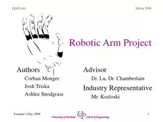
Small-Scale Robotic Arm. Senior Capstone Project Ben Boyle and Kitera Hayes Project Advisor: Dr. Gary Dempsey April 29, 2004. Outline. Objectives Equipment List System Specifications Functional Description Block Diagram System Parameters System Identification

Small-Scale Robotic Arm
E N D
Presentation Transcript
Small-Scale Robotic Arm Senior Capstone Project Ben Boyle and Kitera Hayes Project Advisor: Dr. Gary Dempsey April 29, 2004
Outline • Objectives • Equipment List • System Specifications • Functional Description • Block Diagram • System Parameters • System Identification • Implementation of Controllers • Flexible Rotary Joint • System Limitations • Conclusion • Completed Tasks • Questions
Objectives • Determination of Plant Model • Fast System Response • Wide Command Range (± 90 degrees) • High Stability Margin (GM, PM) • User-friendly Software Interface • Low Resonant Frequency Mode with New Arm
Equipment List • 200 MHz Pentium-based computer • Quanser System • Robotic Arm with Flexible Rotary Joint • Power Amplifier • Software • MATLAB (SIMULINK) • Borland C
System Specifications • Command: ± 90 set points, ± 40 deg/sec velocity • Percent Overshoot = 0 % • Steady-State Error = ± 2 degrees • Phase Margin 70 degrees
Small Scale Robotic Arm Control Command Input Functional Description Positioning Figure 1 - Input/Output Description
Functional Description • Software Interface • Positioning Modes of Operation
Software Block Diagram System (Plant) Figure 2 - Block Diagram of Robotic Arm
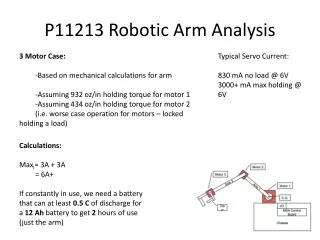
System Parameters • System (Plant) • Amplifier 5 [V] @ 3 [A] • Position Sensor 180 of travel • DC motor 5 [V] • External Gears 5:1 velocity reduction • Internal Gears 14.1:1 velocity reduction • Antialiasing Filter first-order low-pass with pole @ 163 [rad/sec] • Software • 200 [MHz] PC • A/D converter 12 bit plus sign, 5 [V] • D/A converter 12 bit, 5 [V]
System Identification • Closed-loop Results • Open-loop Results • Plant Model Equation • Plant Model Verification
System Identification • Closed-loop Results • Gain k = 0.025 Best Fit • Close to 0% overshoot • Step input of ±20° • DC Gain • Gp(0) = 27°/[V]
E=12 D/A k=0.025 Gp R=20 C=8 Controller voltage=0.2954 System Identification Controller Voltage = (12°)(.025) = 0.295 [V] DC Gain [Gp(0)] = 8°/0.295 [V] = 27°/[V] Figure 3 – DC Gain Calculation of System
System Identification Figure 4 - Gain k = 0.025, Step input of ±20°, Closed-loop (Experimental Results)
System Identification • Open-loop Results • Verify DC gain of plant • Calculate accurate time delay • Help to determine plant model
System Identification Figure 5 - k = 1.0, Step input voltage of 0.74 [V], Open-loop (Experimental Results)
System Identification Input Voltage = 20°/(27°/[V]) = 0.74 [V] (Open-loop) Command Degree Calculation: (K)(Command Voltage)(DC Gain) = Command Degrees Theoretical Command Degrees 20° Experimental Command Degrees 17° Percent Error = 17.6%
System Identification • Plant Gp = k[a/(s+a)2] • c(t) = k[1-e-at - at(e-at)] • @ k = 1.0 and t = 2.86 seconds, c = 11.352° • Double Pole @ a = -0.76 Pole Identification using Laplace Transform
Actual Open-loop Double Pole -0.76 System Identification Typical Open-loop Poles Figure 6 – Second Order System (Poles = -0.76)
-0.0562s 27e 2 (s/0.76 + 1) System Identification • Plant Model Equation: (OPEN-LOOP)
System Identification Plant Model Verification 20.48º Figure 7 - SIMULINK Scope Output for Open-loop System = 20.48º
System Identification Plant Model Verification 8.38º Figure 8 - SIMULINK Scope Output for Closed-loop System = 8.38º
P Controller Figure 9 - Theoretical P Controller Output Figure 10 - P Controller System Output
PI Controller Figure 11 - Theoretical PI Controller Output Figure 12 - PI Controller System Output
PID Controller Figure 13 - Theoretical PID Controller Output Figure 14 - PID Controller System Output
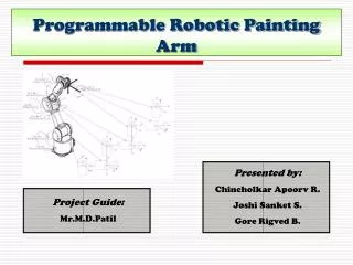
Feed-Forward/PI Controller Figure 15 - Feed-Forward/PI Controller Block Diagram
Feed-Forward/PI Controller Figure 16 - Theoretical FF/PI Controller Output Figure 17 - FF/PI Controller System Output
Controller Comparison P Controller FF/PI Controller Figure 18 - P Controller System Output Figure 19 - FF/PI Controller System Output
Flexible Rotary Joint Figure 20 - P Controller System Output Figure 21 - P Controller Flex Joint System Output
System Limitations • D/A Converter ± 5 [V] • Static Friction • Just matches the applied force to try and prevent motion • Modeling Time delay e-std (linear) • Kinetic Friction • Moving friction with respect to speeds • Inertia • J = (mass)(radius2) • Gravity
System Limitations PENDULUM -B/2J (a) With Friction (b) Without Friction Figure 22(a-b) – Friction Characteristics for Pendulum System
System Limitations Time Delay Tdavg = 56.2 [ms] Figure 23 - Closed-loop Time Delay and % Overshoot Calculations for Varying Gain k
Conclusion • PI Controller is slow • PID Controller does not work • Solution is FF/PI Controller
Completed Tasks • Plant Model and Validation • Proportional, PI, and PID Controllers • FF Controller with PI • User-friendly Software Interface • Future Work • Plant Model for Flexible Rotary Joint • Gripper Motor with Varying Loads • Notch Filter Incorporation