Download

1 / 13
130 likes | 275 Views
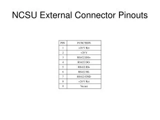
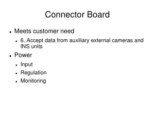
This document outlines the design and functionality of an external connector board that integrates various interfaces like 2x Camera Link and 2x GigE with 10/100 Ethernet capabilities. The board features an RCA output and a USB port, all mounted on a single interface for streamlined routing. Key functionalities include supporting inertial navigation systems (INS) and GNSS, ensuring compatibility with specific customer requirements such as the NovAtel OEMV series. A focus on routing efficiency and power supply options is addressed to meet operational demands.

E N D
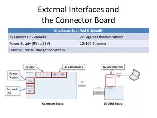
External Interfaces andthe Connector Board 2x GigE 2x Camera Link 10/100 Ethernet Power Supply External INS Connector Board D3 OEM Board
External Interfaces andthe Connector Board Power Supply External INS 2x Camera Link 2x GigE RCA output 10/100 Ethernet USB port Connector Panel
External Interfaces andthe Connector Board • Goal: • All interfaces routed through and mounted on the Connector Board • Reality: • Various different mountings and routings necessary
Interface Routing andConnector Mounting 2x Camera Link External INS Power Supply • 2x Camera Link = nearly full width of Connector Board Connector Panel
Interface Routing andConnector Mounting • GigE mounted on FPGA Board 2x GigE FPGA Board (bottom view) Connector Panel
Interface Routing andConnector Mounting RCA 10/100 Ethernet • RCA and 10/100 Ethernet routed directly to D3 OEM Board 10/100 Ethernet RCA output D3 OEM Board (top view) Connector Panel
Interface Routing andConnector Mounting USB port • USB routed directly to internal GNSS receiver Connector Panel
The Connector Board • Having determined what it needs to do, design could commence Customer Provided Block Diagram
Inertial Navigation System (INS) • Determines: • Direction • Roll, pitch & yaw • Velocity • Inertial Measurement Unit (IMU) • Location • Global Navigation Satellite System (GNSS) • Global Positioning System (GPS) • GLONASS
Global Navigation Satellite System • Customer Specified • NovAtel OEMV-2 or OEMV-3 • RS-232 interface • Different power requirements OEMV-2: 3.3 +5%/-3% VDC OEMV-3: 4.5 to 18 VDC