Download
1 / 46
460 likes | 484 Views
Gain insight into the Deepwater Horizon accident and the factors that led to the catastrophe. Learn from the questionable issues and discover how to prevent future incidents.

E N D
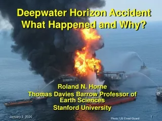
Deepwater Horizon AccidentWhat Happened and Why? Roland N. Horne Thomas Davies Barrow Professor of Earth Sciences Stanford University Photo: US Coast Guard
What and Why? • Understanding the catastrophe is the first step in preventing another. • An important event should be understood by forward-thinking individuals. • Decisions need to be based on knowledge.
Sources • An interpretation of the observations and testimony of others. • House Energy and Environment Subcommittee of the Energy and Commerce Committee Investigation (June) • Transcripts - The Joint United States Coast Guard/Bureau of Ocean Energy Management Investigation (May-Oct) http://www.deepwaterinvestigation.com • BP Deepwater Horizon Accident Investigation Report (Sept 8) • BP Deepwater Horizon Investigation: Preliminary Insights [Halliburton] (Sept 26) • National Academy of Engineering Committee http://sites.nationalacademies.org/BlowoutPrevention • Personal conversations with members of government and industry (May-Oct)
5 Main Topics • The process and equipment of deep-water drilling. • A series of questionable issues. • The ones that mattered in the accident. • How to do it better. • Why do we do it at all?
1. Deep-water Drilling • Riser and BOP • Dynamic positioning or anchoring of vessel • Crew rotation (21/21, 12/12) • Isolation from shore/office • Access for remediation • Multiple contractors • Expense Source: BP Report Sept. 8, 2010
BOP Separation from Rig Sources: US Coast Guard, BP Report Sept. 8, 2010
Dynamic Positioning • Vessel must have power at all times Sources: Cargolaw.com, BP Report Sept. 8, 2010
In the event of DP failure, requires EDS Source: BP Report Sept. 8, 2010
Remotely Operated Vehicle ROV Source: http://www.oceaneering.com
2. Series of Questionable Issues • Casing design • Long string, rather than liner and tie-back • No lockdown sleeve (at time of accident) • Single string over several formations of different pressure • Cement design • Few centralizers • Big casing, small hole • Nitrogen foam cement • No cement-bond log
2. Series of Questionable Issues • Negative pressure test • Unclear procedures • Conducted soon after cementing • Confusing because of unusual spacer • Misunderstood by crew • Flow monitoring • Flows confusing due to offloading • Insufficient response to flow indications • Hydrocarbons entered the riser
2. Series of Questionable Issues • Ignition • Hydrocarbon flow through MGS • Gas entry into engine room, intake not auto • Engine overspeed, power loss, fire • BOP • Crew shut BOP, but failed to seal well • EDS pushed but link to BOP lost in fire • Automatic function didn’t work • ROV operation of BOP didn’t work
3. The Bad Stuff • The cement job failed to seal off the producing reservoir(s). Casing seal failed. • Hydrocarbon inflow was not recognized, and hydrocarbon entered the riser. • Gas ignited on the rig, causing fire and loss of power. • The BOP failed to seal the well.
(a) The Cement Job • There is no question that the cement job failed to isolate the formation. • Unclear why. BP and Halliburton not in agreement. Source: BP Report Sept. 8, 2010
Converting the float collar required excessive pressure (3000 vs. 400-700 psi). • Small pressure window required lightened cement. • Lost circulation zones. • Few centralizers. • No cement bond log run. Source: BP Report Sept. 8, 2010
Frac Gradient Pore Pressure Pressure “Window” • Well pressure must exceed pore pressure. • Well pressure must not exceed frac pressure. • Casing protects shallower formations from deeper pressures. Source: Mark Zoback “Reservoir Geomechanics”
Halliburton Reports • Modeling indicated “severe” channeling could occur across the reservoir with only six centralizers installed • Modeling was also run with 10 centralizers • Channeling was still predicted • Modeling was run with 21 centralizers • No channeling was indicated • Casing was loaded on rig with 6 centralizers • 15 additional centralizers were flown to the rig, but were not to used Modeled with 7 Centralizers Modeled with 21 Centralizers TOC 16,353 TOC 17,259 Source: Halliburton presentation Sept. 26, 2010 Reference: 9.875 X 7 Prod Casing Design Report - 21 Cent.pdf; & 9.875 X 7 Prod Casing Design Report - 6 Cent.pdf; April 15, 2010
16ppg Spacer 14.17ppg SOBM (Mud) 8.6ppg Seawater Influx Seal Assembly Failure Casing Shoe Failure Casing Shoe or Seal Failure? Source: BP Report Sept. 8, 2010
(a) The Cement Job • It is clear that the cement job failed to isolate the producing formation. • It seems likely that the float collar check valves and shoe track cement failed to seal the casing. • The casing shoe can not be recovered from the well.
(b) Flow Condition Not Recognized • Two negative tests conducted, and accepted by the crew as successful. • Negative test interpretation made more difficult by the presence of unusual spacer. • No standard procedure for negative test. • Pit levels confusing because of fluids being offloaded to service vessel.
The Spacer • 425 barrels of mixed lost circulation material LCM, Form-A-Squeeze and Form-A-Set. • Unconventional to use as a spacer, about four times more material than usual. • Dischargeable material, but only if it had been used in the well. • Spacer may have entered kill-line and caused anomalous U-tube pressures.
First test • Annular leaked • Spacer backflowed below BOP • Crossed kill-line Source: BP Report Sept. 8, 2010
Second test • Possible kill line blockage or U-tube • Zero pressure on kill line Source: BP Report Sept. 8, 2010
0PSI 1400PSI Spacer • Second test • Possible kill line blockage or U-tube • Zero pressure on kill line Source: BP Report Sept. 8, 2010
DP pressincreasingat zero flow trip tankemptiedinto line flow outwithoutflow in DP pressincreasingat const flow sheentest spacerapproachessurface Flow diverted overboard,no more flow-out indicator http://www.deepwaterinvestigation.com/go/doc/3043/820875/
HC entersriser DP pressincreasingat zero flow DP pressincreasingat zero flow trip tankemptiedinto line flow outwithoutflow in flow outwithoutflow in DP pressincreasingat const flow DP pressincreasingat zero flow sheentest sheentest spacerapproachessurface flow diverted overboard,no more flow-out indicator spacer fullydisplaced,pumps shut Flow diverted overboard,no more flow-out indicator http://www.deepwaterinvestigation.com/go/doc/3043/820875/
HC entersriser mud overflowsflow line mud shootsup derrick VBRclosed? annular leaking engineoverspeed explosion annular closed gas alarm gas hissing http://www.deepwaterinvestigation.com/go/doc/3043/820875/
(c) Gas Ignited on the Rig • Gas was diverted to the MGS, instead of to the overboard diverter [BP]. • IBOP was not closed [BP]. • Engine room intake closure was not activated automatically on gas alarm [testimony]. • Engine overspeed loss of power (and source of ignition?) [testimony]
Gas Dispersed Over Deck Source: BP Report Sept. 8, 2010
Engine Intakes on Aft Deck Source: Mark Zoback, Deepwater Nautilus
Fire and Gas Alarm Systems • BP Investigation Report: • “A flammable mixture was likely transferred into the engine rooms because the engine room HVAC fans were not designed to shut down automatically on gas detection.” • “There was a high level of reliance upon manual/human intervention in the activation of DH safety systems…” Source: BP Report Sept. 8, 2010
(d) BOP Failed to Seal the Well 3 modes of closure • Manual: • HP line (BSR) • EDS • Automatic: • AMF on loss of power/mux/HP • ROV: • Hot stab • Autoshear Source: BP Report Sept. 8, 2010
Annular BOPgradually opens BOP Response (Impact of Explosions) MUX cables provide electronic communication and electrical power to the BOP control pods. • April 20th • Damage to MUX cables and hydraulic line • Opening of annular BOP Upper Annular Lower AnnularStripping Element • Rig drifted off location • Upward movement of the drill pipe in the BOP Blind Shear Ram Casing Shear Ram(Non Sealing) Upper VBR Middle VBR Lower (Test) VBR Wellhead Connector Source: BP presentation to NAE PanelSept. 26, 2010 Wellhead Sea Bed
BSR activated by Auto-shear BOP Response (After the Explosions) There are several emergency methods of activating the BSR to seal the well. • April 20th • EDS attempts failed to activate BSR • AMF sequence likely failed to activate BSR • April 21st – 22nd • ROV hot stab attempts to close BOP were ineffective • ROV simulated AMF function likely failed to activate BSR • ROV activated auto-shear appears to have activated but did not seal the well • April 25th – May 5th • Further ROV attempts using seabed deployed accumulators were unsuccessful Upper Annular Lower AnnularStripping Element Blind Shear Ram Casing Shear Ram(Non Sealing) Upper VBR Middle VBR Lower (Test) VBR Wellhead Connector Source: BP presentation to NAE PanelSept. 26, 2010 Wellhead Sea Bed
BSR the Only Option • Even if the annulus had been closed, the drill pipe was still open. Source: BP web site
Why AMF Unsuccessful? Source: BP Report Sept. 8, 2010
ROV Operations Source: US Coast Guard
Why ROV Operations Unsuccessful? • Hydraulic leak on BOP Source: BP Report Sept. 8, 2010
Why ROV Operations Unsuccessful? • BSR can only shear drill pipe – not tool joints, casing, or collars. • BSR functioned by EDS(1), AMF and ROV. • If tool joint in bore, cannot cut it. Source: BP Report Sept. 8, 2010 Source: BP Report Sept. 8, 2010
4. How to Do It Better? • Bureau of Ocean Energy Management (was Minerals Management Service MMS) • US Coast Guard • American Petroleum Institute • “Flag State” (Republic of Marshall Islands for Deepwater Horizon)
My Suggestions • A second blind shear ram (BSR). • Independent BOP activation control (audio wave activation). • More comprehensive data from BOP (position of rams, contents of tubulars). • Real-time modeling of fluids and pressures in tubulars (as in simulations). • Complete off-site transmission of data.
5. Why Don’t We Stop Doing This? • Gulf of Mexico accounts for 30% of US oil production, a 33% increase since 2008. • 80% of Gulf of Mexico oil production is due to deepwater oil fields. • One quarter of US oil production comes from deepwater oil fields. • Global deepwater production capacity has tripled since 2000. Source: Shell presentation, August 25, 2010
Can It Be Done Safely? • Gulf of Mexico (1/1/2000 – 12/31/2009) 8499 wells spudded • 5224 were development wells • 3426 were exploratory wells • 21 were research/other wells • 6365 were in water depths < 500 feet • 186 were in water depths 501 – 1000 feet • 1948 were in water depths > 1000 feet Source: BOEM presentation, August 12, 2010