Download
1 / 35
360 likes | 479 Views
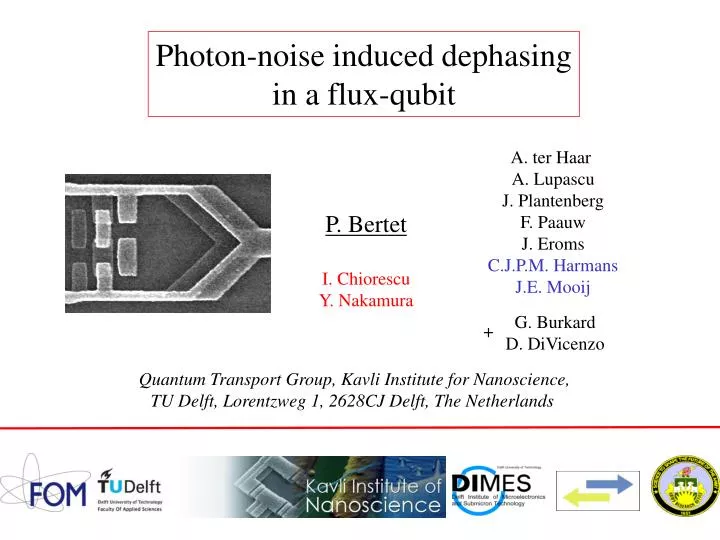
Photon-noise induced dephasing in a flux-qubit. A. ter Haar A. Lupascu J. Plantenberg F. Paauw J. Eroms C.J.P.M. Harmans J.E. Mooij. P. Bertet. I. Chiorescu Y. Nakamura. G. Burkard D. DiVicenzo. +. Quantum Transport Group, Kavli Institute for Nanoscience,

E N D
Photon-noise induced dephasing in a flux-qubit A. ter Haar A. Lupascu J. Plantenberg F. Paauw J. Eroms C.J.P.M. Harmans J.E. Mooij P. Bertet I. Chiorescu Y. Nakamura G. Burkard D. DiVicenzo + Quantum Transport Group, Kavli Institute for Nanoscience, TU Delft, Lorentzweg 1, 2628CJ Delft, The Netherlands
Very slow and strongly coupled fluctuators E. Paladino et al., Phys. Rev. Lett. 88, 228304 (2002) Underdamped modes strongly coupled to qubit M. Thorwart et al., Chem. Phys. 296, 333 (2004) Introduction (weak coupling) Dephasing ?
Qubit dephased by photon noise Temperature T Quality factor Q Dispersive regime : Shift of oscillator frequency Coupling Shift of qubit frequency
Qubit dephased by photon noise Photon fluctuations around Qubit frequency Phase shift Dephasing factor with A. Blais et al., PRA 69, 062320 (2004) Dephasing time Tf
Qubit dephased by photon noise Photon shot noise 1) Oscillator driven by a coherent field Measurement induced dephasing D. Schuster et al., PRL 94, 123602 (2005) Cf also M. Brune et al., PRL 76, 1800 (1996) 2) Thermal fluctuations in the non-driven oscillator Thermal field :
Flux-qubit Our circuit : DC-SQUID plasma mode Our measurements : qubit coherence limited by thermal fluctuations in plasma mode 1) Quantitative agreement with formula 2) Thanks to our circuit geometry, coupling constants Optimal points (with respect to photon noise) whenever Flux-qubit coupled to SQUID plasma mode
gQ The flux-qubit Al/AlOx/Al junctions by shadow evaporation + e-beam lithography Josephson junctions 1 control parameter
80 |3> |2> 40 |1> Frequency(GHz) qubit 0 |0> 0.48 0.50 0.52 gQ/2p Qubit energy levels EJ=225GHz EC=7.2GHz a=0.76
+Ip 300 I1 I(nA) 0 I0 -Ip -300 -0.02 0.00 0.02 |1> (gQ-p)/2p |0> Persistent-current Property of states |0> and |1> : |0> |1> Useful to measure the qubit state
10 01 5 D 0 0.5 gQ/2p Two-level approximation Flux-noise optimal point (GHz) n (cf Saclay) Frequency In the basis,
Microwave pulse Dt Fx+dFxcos(2pnt+f) Rotation axis : (f,y) a dFx Angle : Arbitrary state Control of the qubit state
) A m ( 4 Ic 0 0 1 F F / Sq 0 Persistent-current and detection of the qubit state Our detector : a hysteretic DC-SQUID as on-chip comparator
IC depends on qubit state (i) Theoretical |1> 100 relaxation Pswitch (%) 50 |0> 0 P(1)=Psw 5.4 5.6 m Current I A b ( ) P(1)aPsw Persistent-current and detection of the qubit state Qubit inductively coupled to SQUID
Persistent-current and detection of the qubit state SQUID shunted by a capacitor PLASMA MODE
Coupling of the qubit and the plasma mode dJ/dIb(Ib) M Circ current J Plasma mode current qubit Complex : 2 different effects : a) Effective inductive coupling with tunable mutual inductance b) Flux dependent SQUID Josephson inductance
SQUID circulating current dJ/dIb=0 dJ/dIb(Ib) Ideal symmetric SQUID : dJ/dIb(0)=0 Decoupling current Including asymmetries :
1) Measurement shift 2 1 2) Coupling hamiltonian Energy (GHz) inductive Flux-dependent Josephson inductance Current (mA) -0.02 0.00 0.02 NON RESONANT (e/Ip)e Coupling of the qubit and the plasma mode
The sample Ib Microwave antenna V Csh G. Burkard et al., cond-mat/0405273
The setup 3k 1k
trigger Ib pulse time Microwave pulse at frequency f read-out Dt 25 20 15 Larmor frequency (GHz) 10 B 5 0 -0.01 0.00 0.01 (Fx-F0/2)/F0 Parameters : D=5.85GHz, Iq=270nA Qubit spectroscopy
Plasma mode spectroscopy Microwave pulse at frequency f Ib time Switching probability enhancement if f=np : resonant activation Resonant activation peak : Typical width : 20-50MHz Csh=12pF, L=170pH (design) P. Bertet et al., Phys. Rev. B 70, 100501 (2004)
Ib=0.6mA Ib* 6.5 6.0 Frequency (GHz) Ib=0mA 5.5 -0.001 0.000 0.001 F F F ( - /2 ) / x 0 0 Evaluating the coupling constants Measure l(Ib) Spectroscopy
0.0 g2 Coupling (GHz) g1 -0.2 Ib* 0.0 0.3 0.6 m I ( A ) b Evaluating the coupling constants Measure l(Ib) Spectroscopy Ib*
Frequency shift dn0 due to g2 -20MHz 0MHz e=0 +26MHz Shift has same sign as epsilon Frequency shift Frequency shift dn0 due to g1 ac-Zeeman shift. Always >0
Frequency shift Optimal point For flux-noise Optimal point for photon noise dn0=0 Quantitative prediction : optimal point for photon noise Optimal point for flux/current noise
78 Pswitch (%) f2,w2 f1,w1 68 5.52 5.56 5.60 Freq F(GHz) Characterizing decoherence (1) : spectroscopy Low-power spectroscopy Rabi oscillations 5 types of experiments : T1 measurements Ramsey fringes Spin-echo measurements Thermal photon noise : « high frequency » At decoupled optimal point (Ib=Ib*,e=0) Strongly coupled 2-level fluctuator
200 80 100 60 0 1 2 Pulse duration Dt (ms) 0.00 0.06 m Pulse length ( s ) Characterizing decoherence (2) : Rabi oscillations At decoupled optimal point (Ib=Ib*,e=0) nMW=nQ Dt Non-exponential because low-frequency noise Pswitch (%)
80 Pswitch (%) 60 0 10 20 m s Delay Dt ( ) Characterizing decoherence (3) : T1 measurements At decoupled optimal point (Ib=Ib*,e=0) p Dt - Exponential decay
Characterizing decoherence (4) : Ramsey fringes 160 140 120 Pswitch (%) 100 80 60 0.0 0.1 0.2 0.3 0.4 Delay between pulses (microseconds) Tp/2 At decoupled optimal point (Ib=Ib*,e=0) p/2 p/2 Tp/2 nMW-nQ Difficult to extract dephasing time …
Tp/2=2.2ms Tp/2/2 p p/2 p/2 Dt Tp/2 Bertet et al., cond-mat/0412485 Characterizing decoherence (5) : spin-echo sequence
T1 dependence on Ib Ib* Away from Ib*, T1 limited by coupling to measuring circuit
Best coherence : e=em<0 Ib=0mA g1=80MHz NOT LIMITED by flux-noise Spin-echo and t2 dependence on Ib and e Techo t2=2/p(w1+w2) Ib=Ib* g1=0 Best coherence : e=0 (optimal point)
Decoherence due to qubit-plasma mode coupling em dn0=0 Dephasing minimum for spin-echo and Ramsey when dn0=0 Quantum coherence limited by photon noise
Spin-echo and t2 dependence T=70mK, Q=150 Ib=Ib* g1=0 Ib=0mA g1=80MHz Quantitative agreement
Conclusion Dephasing due to thermal fluctuations of the photon number in an underdamped resonator coupled to the qubit : very general situation Case of a flux-qubit coupled to the plasma mode of its SQUID detector By tuning coupling constants, could decouple qubit from photon noise Long spin-echo time (4ms) at optimal bias point Quantitative agreement with simple model for spin-echo time 2 questions : - mechanism for low-freq noise ? (charge or critical current noise ?) - effect of dispersive shifts in usual spin-boson model ?