Download
1 / 21
210 likes | 937 Views
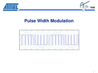
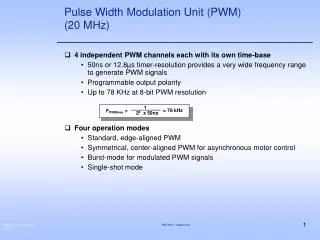
1. = 78 kHz. F PWMmax =. 2 8 x 50ns. Pulse Width Modulation Unit (PWM) (20 MHz). 4 independent PWM channels each with its own time-base 50ns or 12.8µs timer-resolution provides a very wide frequency range to generate PWM signals Programmable output polarity

E N D
1 = 78 kHz FPWMmax = 28 x 50ns Pulse Width Modulation Unit (PWM)(20 MHz) • 4 independent PWM channels each with its own time-base • 50ns or 12.8µs timer-resolution provides a very wide frequency range to generate PWM signals • Programmable output polarity • Up to 78 KHz at 8-bit PWM resolution • Four operation modes • Standard, edge-aligned PWM • Symmetrical, center-aligned PWM for asynchronous motor control • Burst-mode for modulated PWM signals • Single-shot mode HOT167-1 Version 2.0
PWM unitFrequencies and Resolution PMW Unit Frequencies and Resolution in Mode 0 Operation (EDGE-ALIGNED) Resolution 8 Bit 10 Bit 12 Bit 14 Bit 16 Bit Input Clock(CPU @ 20 MHz) CPU Clock (50ns Resolution) 78.1 KHz 19.5 KHz 4.88 KHz 1.22 KHz 305 Hz CPU Clock / 64 (3.2µs Res.) 1.22 KHz 305 Hz 76.3 Hz 13.1 Hz 4.77 Hz PMW Unit Frequencies and Resolution in Mode 1 Operation (SYMMETRICAL) Resolution 8 Bit 10 Bit 12 Bit 14 Bit 16 Bit Input Clock(CPU @ 20 MHz) CPU Clock (50ns Resolution) 39.1 KHz 9.77 KHz 2.44 KHz 610 Hz 152.6 Hz CPU Clock / 64 (3.2µs Res.) 610 Hz 152.6 Hz 38.15 Hz 9.54 Hz 2.4 Hz HOT167-1 Version 2.0
INTR Flag Input Mode Control PWM unitFunction Diagram Period Register PP0-PP3 Shadow Register Comparator Run Enable 20 MHz up/down,clear Timer PT0-PT3 78 KHz PWM Outputs Output Polarity Enable at 20 MHz CPU Clock Comparator Shadow Register Pulse Width Reg. PW0-PW3 4 identical PWM Channels with common Interrupt Control Register HOT167-1 Version 2.0
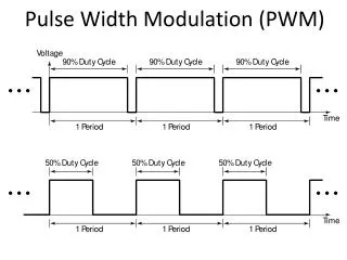
PWM unit - Mode 0 and 1 PWM Mode 0: Standard PWM’s or Edge-Aligned PWM’s PWM Mode 1: Symmetrical or Center-Aligned PWM’s Contents of the Period Register (PPx) Timer Period Timer Period Timer Period Contents of the PWx Register Contents of the PWx Register Interrupt Request and Latch of the Shadow Register IR and Latch of the Shadow Register PWM Signal PWM Signal If all channels are programmed to mode 0, edge-aligned PWM signals will be generated. A duty cycle from 0 to 100% is programmable If all channels are programmed to mode 1, center-aligned PWM signals will be generated. A duty cycle from 0 to 100% is programmable Possible PWM Signals from other channels programmed to the same mode: PWMx PWMy HOT167-1 Version 2.0
PWM unit - Burst Mode / Single Shot Mode Burst Mode : Burst Sequence by combining PWM channel 0 and 1 Single Shot : Only one PWM Pulse is generated Mode available for channel 2 and 3 Period Value Period Value Timer Period PT0 Timer Period PeriodValue Pulse widthValue Timer is automatically stopped Timer is released by Software again Internal Signal of Channel 0 Output Signal Period of Timer PT1 The Timer can be dynamically changed to lengthen (retrigger) or shorten the output pulse Int. Signal of Channel 1 Output Result: Channel 1 is modulated by Channel 0 HOT167-1 Version 2.0
Overview Port Structure • The Port lines provide the connection to the external world • 111 Port lines on the C167 • All Port lines are individually addressable and all I/0 lines are independently programmable for input or output • Each Port line is dedicated to one or more peripheral functions • Each Port is protected with fast diodes • Programmable open drain buffers • P2, 3, 6, 7, 8 on the C167 HOT167-1 Version 2.0
Overview Port Structure VCC Open Drain Control Alternate Enable Direction Register Alternate Output Write Port Pin Output Latch Buffer Mux Read Direction Internal Bus Buffer Mux Vss Input Latch ESD structure Clock Alternate Input HOT167-1 Version 2.0
Exercise 7PWM_1 - Two edge-alignedPWM Signals with the PWM unit • Objective: • Generate an edge-aligned 25% duty cycle PWM Signal using PWM channel 1 (Period: 1ms) • Generate an edge-aligned 50% duty cycle PWM Signal using PWM channel 3 (Period: 1ms) HOT167-1 Version 2.0
Exercise 7PWM_1- DAvE Configurations • Start DAvE • Create new Project with microcontroller C167CR/CS* • Project name: 7pwm_1 • Select project path: c:\hot167_1\7pwm_1 • Project Settings: • General: • Select Keil Compiler, SMALL model • System Clock: • External Oscillator Frequency: Set to 5 MHz • Startup Configuration: • Bus Type after Reset: Set to 16 bit DEMUX • Write Configuration: Pin #WR and #BHE operates as #WRL and #WRH • Save & close * C167CS not yet supported by DAvE V1.0 CD ROM. See “Hints regarding DAvE.” HOT167-1 Version 2.0
Exercise 7PWM_1 - DAvE Configurations (cont.) • Configure PWM: • Control: • Configure Channel 1: • General: Use PWM Channel 1 • PWM Channel Mode Control: Standard PWM (edge aligned) • Channel Output Enable: Enable Channel 1 output signal • PWM Timer Start Control: Start PWM Timer 1 after init • Period: Required Period: 1000 us • Duty Cycle: Required Duty Cycle: 25% • Save & Close • Configure Channel 3: • General: Use PWM Channel 3 • PWM Channel Mode Control: Standard PWM (edge aligned) • Channel Output Enable: Enable Channel 3 output signal • PWM Timer Start Control: Start PWM Timer 3 after init • Period: Required Period: 1000 us • Duty Cycle: Required Duty Cycle: 50% • Save & Close HOT167-1 Version 2.0
Exercise 7PWM_1 - DAvE Configurations (cont.) • Configure PWM (cont.) • Functions: • Include PWM initialization function PWM_vInit • Save & Close • Configure Port 7: • Port 7: • DAvE has reserved P7.1 and P7.3 for the PWM alternate functions with 0 as initial output • Don’t enable general purpose IO! • Functions: • Include port initialization function IO_vInit • Save & close • Generate Code HOT167-1 Version 2.0
Exercise 7PWM_1 - µVision2 Configurations • Start µVision2 • New Project • Add Files: • Go to Project | Targets, Groups, Files… • Click ‘Groups / Add Files’ • Select ‘Source Group 1’ • Click ‘Add Files to Group’ • Select all C files and click ‘add’ • Enter file name ‘start.asm’, click ‘add’ (Assembler Startup File) • Click ‘Close’ and ‘OK’ • Double-click all files in the Project Window to open them • Select Target Hardware (kitCON-167): • Go to Project | Options for Target ‘Target 1’ • Go to ‘Debug’ tab • Click ‘Settings’ (upper right hand corner) • Monitor configuration: select ‘Phytec KC167’ • Click ‘OK’ twice HOT167-1 Version 2.0
Exercise 7PWM_1 -µVision2 Configurations (cont.) • Edit MAIN.C: • include endless loop in main(): // USER CODE BEGIN (Main,2) while(1) {}; // USER CODE END HOT167-1 Version 2.0
Exercise 7PWM_1 - Running the Program • Reset Target Hardware (Press Reset Button on Starter Kit) • Build Project (Project | Rebuild Target) • Run integrated Debugger from within µVision2 • Debug | Start / Stop Debug Session (click ‘OK’ when prompted) • The Debugger will load the Keil Monitor into the kitCON-167’s RAM via bootstrap loader • Object file c:\hot167_1\7pwm_1\7pwm_1 will be loaded automatically and the debugger will go to main(). • Go! (Debug | Go) • Program Verification: Connect Scope to • P7.1 / POUT1 (connector X3 pin 121) • P7.3 / POUT3 (connector X3 pin 122) HOT167-1 Version 2.0
Exercise 7PWM_2 - Two center-alignedPWM Signals with the PWM unit • Objective: • Generate a center-aligned 25% duty cycle PWM Signal using PWM channel 1 (Period: 250 us) • Generate a center-aligned 50% duty cycle PWM Signal using PWM channel 3 (Period: 250us) HOT167-1 Version 2.0
Exercise 7PWM_2 - DAvE Configurations • Start DAvE • Create new Project with microcontroller C167CR/CS* • Project name: 7pwm_2 • Select project path: c:\hot167_1\7pwm_2 • Project Settings: • General: • Select Keil Compiler, SMALL model • System Clock: • External Oscillator Frequency: Set to 5 MHz • Startup Configuration: • Bus Type after Reset: Set to 16 bit DEMUX • Write Configuration: Pin #WR and #BHE operates as #WRL and #WRH • Save & close * C167CS not yet supported by DAvE V1.0 CD ROM. See “Hints regarding DAvE.” HOT167-1 Version 2.0
Exercise 7PWM_2 - DAvE Configurations (cont.) • Configure PWM: • Control: • Configure Channel 1: • General: Use PWM Channel 1 • PWM Channel Mode Control: Symmetrical PWM(center aligned) • Channel Output Enable: Enable Channel 1 output signal • PWM Timer Start Control: Start PWM Timer 1 after init • Period: Required Period: 250 us • Duty Cycle: Required Duty Cycle: 25% • Save & Close • Configure Channel 3: • General: Use PWM Channel 3 • PWM Channel Mode Control: Symmetrical PWM(center aligned) • Channel Output Enable: Enable Channel 3 output signal • PWM Timer Start Control: Start PWM Timer 3 after init • Period: Required Period: 250 us • Duty Cycle: Required Duty Cycle: 50% • Save & Close HOT167-1 Version 2.0
Exercise 7PWM_2 - DAvE Configurations (cont.) • Configure PWM (cont.) • Functions: • Include PWM initialization function PWM_vInit • Save & Close • Configure Port 7: • Port 7: • DAvE has reserved P7.1 and P7.3 for the PWM alternate functions with 0 as initial output • Functions: • Include port initialization function IO_vInit • Save & close • Generate Code HOT167-1 Version 2.0
Exercise 7PWM_2 - µVision2 Configurations • Start µVision2 • Open Project c:\hot167_1\7pwm_1\7pwm_1.uv2 (Project | Open Pr.) • Add Files: • Go to Project | Targets, Groups, Files… • Click ‘Groups / Add Files’ • Select ‘Source Group 1’ • Click ‘Add Files to Group’ • Select all C files and click ‘add’ • Enter file name ‘start.asm’, click ‘add’ (Assembler Startup File) • Click ‘Close’ and ‘OK’ • Double-click all files in the Project Window to open them • Select Target Hardware (kitCON-167): • Go to Project | Options for Target ‘Target 1’ • Go to ‘Debug’ tab • Click ‘Settings’ (upper right hand corner) • Monitor configuration: select ‘Phytec KC167’ • Click ‘OK’ twice HOT167-1 Version 2.0
Exercise 7PWM_2 -µVision2 Configurations (cont.) • Edit MAIN.C: • include endless loop in main(): // USER CODE BEGIN (Main,2) while(1) {}; // USER CODE END HOT167-1 Version 2.0
Exercise 7PWM_2 - Running the Program • Reset Target Hardware (Press Reset Button on Starter Kit) • Build Project (Project | Rebuild Target) • Run integrated Debugger from within µVision2 • Debug | Start / Stop Debug Session (click ‘OK’ when prompted) • The Debugger will load the Keil Monitor into the kitCON-167’s RAM via bootstrap loader • Object file c:\hot167_1\7pwm_1\7pwm_1 will be loaded automatically and the debugger will go to main(). • Go! (Debug | Go) • Program Verification: Connect Scope to • P7.1 / POUT2 (connector X3 pin 121) • P7.3 / POUT4 (connector X3 pin 123) HOT167-1 Version 2.0