Download
1 / 47
470 likes | 491 Views
Learn about lighting correction, perspective normalization, and coordinate systems. Explore projection taxonomy and illumination models for photorealistic rendering in computer graphics.

E N D
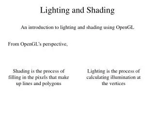
http://www.ugrad.cs.ubc.ca/~cs314/Vjan2005 Lighting and ShadingWeek 4, Fri Jan 28
Reading (today, Mon, Wed) • FCG • Chapter 8 • RB • Chapter Lighting
Correction from last time • row vectors not column vectors might have been confusing • but they’re mathematically equivalent
Perspective Warp • matrix formulation (with column vectors) • preserves relative depth (third coordinate) • what does mean?
Review: NDC to Viewport Transformation • 2D scaling and translation (-1,-1) (1,1) (w,h) DCS b NDCS a y x (0,0) OpenGL glViewport(x,y,a,b); default: glViewport(0,0,w,h);
Review: Perspective Normalization • perspective viewing frustum transformed to cube • orthographic rendering of cube produces same image as perspective rendering of original frustum
Review: Perspective Normalization normalized device clipping • distort such that orthographic projection of distorted objects is desired persp projection • separate division from standard matrix multiplies • clip after warp, before divide • division: normalization viewing CCS VCS NDCS projection transformation perspective division alter w / w
Review: Coordinate Systems http://www.btinternet.com/~danbgs/perspective/
Review: Perspective Derivation VCS NDCS y=top (1,1,1) z x=left y y z (-1,-1,-1) x z=-near y=bottom z=-far x x=right
Review: Field-of-View Formulation • FOV in one direction + aspect ratio (w/h) • also set near, far x Frustum -z z=-n z=-f
Projection Taxonomy planar projections perspective: 1,2,3-point parallel orthographic oblique cavalier cabinet axonometric: isometric dimetric trimetric top, front, side http://ceprofs.tamu.edu/tkramer/ENGR%20111/5.1/20
one-point perspective Perspective Projections • classified by vanishing points two-point perspective three-point perspective
Parallel Projection • projectors are all parallel • vs. perspective projectors that converge • orthographic: projectors perpendicular to projection plane • oblique: projectors not necessarily perpendicular to projection plane Orthographic Oblique
Axonometric Projections • projectors perpendicular to image plane • select axis lengths http://ceprofs.tamu.edu/tkramer/ENGR%20111/5.1/20
Oblique Projections • projectors oblique to image plane • select angle between front and z axis • lengths remain constant • both have true front view • cavalier: distance true • cabinet: distance half d / 2 y y d d d x z x z cabinet cavalier
Demos • Tuebingen applets from Frank Hanisch • http://www.gris.uni-tuebingen.de/projects/grdev/doc/html/etc/AppletIndex.html#Transformationen
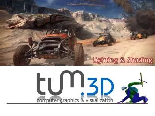
Goal model interaction of light with matter in a way that appears realistic and is fast • phenomenological reflection models • ignore real physics, approximate the look • simple, non-physical • Phong, Blinn-Phong • physically based reflection models • simulate physics • BRDFs: Bidirectional Reflection Distribution Functions
Photorealistic Illumination [electricimage.com]
Photorealistic Illumination [electricimage.com]
Illumination • transport of energy from light sources to surfaces & points • includes directand indirect illumination Images by Henrik Wann Jensen
Components of Illumination • two components: light sources and surface properties • light sources (or emitters) • spectrum of emittance (i.e., color of the light) • geometric attributes • position • direction • shape • directional attenuation • polarization
Components of Illumination • surface properties • reflectance spectrum (i.e., color of the surface) • subsurface reflectance • geometric attributes • position • orientation • micro-structure
thermometer/eye reflective objects Illumination as Radiative Transfer • radiative heat transfer approximation • substitute light for heat • light as packets of energy (photons) • particles not waves • model light transport as packet flow energypackets heat/light source
single slit single slit light particles new wavefront light waves bent ray?! Light Transport Assumptions • geometrical optics (light is photons not waves) • no diffraction • no polarization (some sunglasses) • light of all orientations gets through • no interference (packets don’t interact) • which visual effects does this preclude?
Light Transport Assumptions II • color approximated by discrete wavelengths • quantized approx of dispersion (rainbows) • quantized approx of fluorescence (cycling vests) • no propagation media (surfaces in vacuum) • no atmospheric scattering (fog, clouds) • some tricks to simulate explicitly • no refraction (mirages) • light travels in straight line • no gravity lenses
Light Transport Assumptions III • light travels in straight line • no gravity lenses • superposition (lights can be added) • no nonlinear reflection models • nonlinearity handled separately
Light Sources and Materials • appearance depends on • light sources, locations, properties • material (surface) properties • viewer position • local illumination • compute at material, from light to viewer • global illumination (later in course) • ray tracing: from viewer into scene • radiosity: between surface patches
Illumination in the Pipeline • local illumination • only models light arriving directly from light source • no interreflections and shadows • can be added through tricks, multiple rendering passes • light sources • simple shapes • materials • simple, non-physical reflection models
Light Sources • types of light sources • glLightfv(GL_LIGHT0,GL_POSITION,light[]) • directional/parallel lights • real-life example: sun • infinitely far source: homogeneous coord w=0 • point lights • same intensity in all directions • spot lights • limited set of directions: • point+direction+cutoff angle
Light Sources • area lights • light sources with a finite area • more realistic model of many light sources • not available with projective rendering pipeline, (i.e., not available with OpenGL)
Light Sources • ambient lights • no identifiable source or direction • hack for replacing true global illumination • (light bouncing off from other objects)
Ambient Light Sources • scene lit only with an ambient light source Light PositionNot Important Viewer PositionNot Important Surface AngleNot Important
Directional Light Sources • scene lit with directional and ambient light Light PositionNot Important Surface AngleImportant Viewer PositionNot Important
Point Light Sources • scene lit with ambient and point light source Light PositionImportant Viewer PositionImportant Surface AngleImportant
Light Sources • geometry: positions and directions • standard: world coordinate system • effect: lights fixed wrt world geometry • demo: http://www.xmission.com/~nate/tutors.html • alternative: camera coordinate system • effect: lights attached to camera (car headlights) • points and directions undergo normal model/view transformation • illumination calculations: camera coords
Types of Reflection • specular (a.k.a. mirror or regular) reflection causes light to propagate without scattering. • diffuse reflection sends light in all directions with equal energy. • mixed reflection is a weighted combination of specular and diffuse.
Types of Reflection • retro-reflection occurs when incident energy reflects in directions close to the incident direction, for a wide range of incident directions. • gloss is the property of a material surface that involves mixed reflection and is responsible for the mirror like appearance of rough surfaces.
Reflectance Distribution Model • most surfaces exhibit complex reflectances • vary with incident and reflected directions. • model with combination + + = specular + glossy + diffuse = reflectance distribution
shadow shadow Masked Light Surface Roughness • at a microscopic scale, all real surfaces are rough • cast shadows on themselves • “mask” reflected light:
Surface Roughness • notice another effect of roughness: • each “microfacet” is treated as a perfect mirror. • incident light reflected in different directions by different facets. • end result is mixed reflectance. • smoother surfaces are more specular or glossy. • random distribution of facet normals results in diffuse reflectance.
Physics of Reflection • ideal diffuse reflection • very rough surface at the microscopic level • real-world example: chalk • microscopic variations mean incoming ray of light equally likely to be reflected in any direction over the hemisphere • what does the reflected intensity depend on?
Lambert’s Cosine Law • ideal diffuse surface reflection the energy reflected by a small portion of a surface from a light source in a given direction is proportional to the cosine of the angle between that direction and the surface normal • reflected intensity • independent of viewing direction • depends on surface orientation wrt light • often called Lambertian surfaces
Lambert’s Law intuitively: cross-sectional area of the “beam” intersecting an elementof surface area is smaller for greater angles with the normal.
Computing Diffuse Reflection • angle between surface normal and incoming light is angle of incidence: Idiffuse = kd Ilightcos • in practice use vector arithmetic Idiffuse = kd Ilight(n • l) kd : diffuse component ”surface color” l n
Diffuse Lighting Examples • Lambertian sphere from several lighting angles: • need only consider angles from 0° to 90° • why? • demo: Brown exploratory on reflection