Download
1 / 34
340 likes | 555 Views
http://www.ugrad.cs.ubc.ca/~cs314/Vjan2005. Lighting and Shading Week 5, Wed Feb 2. News: Homework. homework correction: questions 13-16 should use: unit square has points A=(0,0,0,1), B=(0,1,0,1), C=(0,1,1,1), D=(0,0,1,1) in world coordinates homework clarification: question 1

E N D
http://www.ugrad.cs.ubc.ca/~cs314/Vjan2005 Lighting and ShadingWeek 5, Wed Feb 2
News: Homework • homework correction: questions 13-16 should use: • unit square has points A=(0,0,0,1), B=(0,1,0,1), C=(0,1,1,1), D=(0,0,1,1) in world coordinates • homework clarification: question 1 • C_i is down one-half unit and sideways one unit.
News: Project Handin • when handing after the deadline, handin has this unfriendly warning message • Checking that handin was successful ... /cs/csbox/user FAILED to find user a1b2. Your files DO NOT appear to be handed in successfully • Do you want to cancel? • don’t panic • go ahead and complete the handin, do not cancel! • your submission will be put in the LATE directory
Review: Reflectance • specular: perfect mirror with no scattering • gloss: mixed, partial specularity • diffuse: all directions with equal energy + + = specular + glossy + diffuse = reflectance distribution
l n Review: Reflection Equations Idiffuse = kd Ilight(n • l) • 2 ( N (N · L)) – L = R
Clarification: Calculating The RVector N • P = N cos q =projection of L onto N • why is P = N cos q, not L cos q? • N and R and L are unit length • difference between • length of projection of u onto v • scalar: |u| cos q • in this case length of u is 1 • cos q • projection of u onto v • vector in direction of v, with scale factor • scale depends on angle between u and v, length of u • v |u| cos q • in this case length of u is 1 • v cos q P L R q scalar length!
n h v l Review: Reflection Equations 2 • Blinn improvement • full Phong lighting model • combine ambient, diffuse, specular components
Review: Lighting • lighting models • ambient • normals don’t matter • Lambert/diffuse • angle between surface normal and light • Phong/specular • surface normal, light, and viewpoint
Lighting in OpenGL • light source: amount of RGB light emitted • value represents percentage of full intensitye.g., (1.0,0.5,0.5) • every light source emits ambient, diffuse, and specular light • materials: amount of RGB light reflected • value represents percentage reflectede.g., (0.0,1.0,0.5) • interaction: multiply components • red light (1,0,0) x green surface (0,1,0) = black (0,0,0)
Lighting in OpenGL glLightfv(GL_LIGHT0, GL_AMBIENT, amb_light_rgba ); glLightfv(GL_LIGHT0, GL_DIFFUSE, dif_light_rgba ); glLightfv(GL_LIGHT0, GL_SPECULAR, spec_light_rgba ); glLightfv(GL_LIGHT0, GL_POSITION, position); glEnable(GL_LIGHT0); glMaterialfv( GL_FRONT, GL_AMBIENT, ambient_rgba ); glMaterialfv( GL_FRONT, GL_DIFFUSE, diffuse_rgba ); glMaterialfv( GL_FRONT, GL_SPECULAR, specular_rgba ); glMaterialfv( GL_FRONT, GL_SHININESS, n ); • warning: glMaterial is expensive and tricky • use cheap and simple glColor when possible • see OpenGL Pitfall #14 from Kilgard’s list http://www.opengl.org/resources/features/KilgardTechniques/oglpitfall/
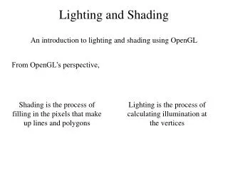
Lighting vs. Shading • lighting • process of computing the luminous intensity (i.e., outgoing light) at a particular 3-D point, usually on a surface • shading • the process of assigning colors to pixels • (why the distinction?)
Applying Illumination • we now have an illumination model for a point on a surface • if surface defined as mesh of polygonal facets, which points should we use? • fairly expensive calculation • several possible answers, each with different implications for visual quality of result
Applying Illumination • polygonal/triangular models • each facet has a constant surface normal • if light is directional, diffuse reflectance is constant across the facet. • why?
Flat Shading • simplest approach calculates illumination at a single point for each polygon • obviously inaccurate for smooth surfaces
Flat Shading Approximations • if an object really is faceted, is this accurate? • no! • for point sources, the direction to light varies across the facet • for specular reflectance, direction to eye varies across the facet
Improving Flat Shading • what if evaluate Phong lighting model at each pixel of the polygon? • better, but result still clearly faceted • for smoother-looking surfaceswe introduce vertex normals at eachvertex • usually different from facet normal • used onlyfor shading • think of as a better approximation of therealsurface that the polygons approximate
Vertex Normals • vertex normals may be • provided with the model • computed from first principles • approximated by averaging the normals of the facets that share the vertex
Gouraud Shading • most common approach, and what OpenGL does • perform Phong lighting at the vertices • linearly interpolate the resulting colors over faces • along edges • along scanlines edge: mix of c1, c2 C1 does this eliminate the facets? C3 C2 interior: mix of c1, c2, c3 edge: mix of c1, c3
Gouraud Shading Artifacts • often appears dull, chalky • lacks accurate specular component • if included, will be averaged over entire polygon C1 C1 C3 C3 C2 this vertex shading spread over too much area C2 this interior shading missed!
Gouraud Shading Artifacts • Mach bands • eye enhances discontinuity in first derivative • very disturbing, especially for highlights
C1 C4 C3 C2 Discontinuity in rateof color changeoccurs here Gouraud Shading Artifacts • Mach bands
Gouraud Shading Artifacts • perspective transformations • affine combinations only invariant under affine, not under perspective transformations • thus, perspective projection alters the linear interpolation! Imageplane Z – into the scene
Gouraud Shading Artifacts • perspective transformation problem • colors slightly “swim” on the surface as objects move relative to the camera • usually ignored since often only small difference • usually smaller than changes from lighting variations • to do it right • either shading in object space • or correction for perspective foreshortening • expensive – thus hardly ever done for colors
Phong Shading • linearly interpolating surface normal across the facet, applying Phong lighting model at every pixel • same input as Gouraud shading • pro: much smoother results • con: considerably more expensive • not the same as Phong lighting • common confusion • Phong lighting: empirical model to calculate illumination at a point on a surface
Phong Shading • linearly interpolate the vertex normals • compute lighting equations at each pixel • can use specular component N1 remember: normals used in diffuse and specular terms discontinuity in normal’s rate of change harder to detect N4 N3 N2
Phong Shading Difficulties • computationally expensive • per-pixel vector normalization and lighting computation! • floating point operations required • lighting after perspective projection • messes up the angles between vectors • have to keep eye-space vectors around • no direct support in hardware • but can be simulated with texture mapping
Shading Artifacts: Silhouettes • polygonal silhouettes remain Gouraud Phong
i Shading Artifacts: Orientation • interpolation dependent on polygon orientation • view dependence! A Rotate -90oand colorsame point B C B A D D C Interpolate betweenCD and AD Interpolate betweenAB and AD
Shading Artifacts: Shared Vertices vertex B shared by two rectangles on the right, but not by the one on the left C H D first portion of the scanlineis interpolated between DE and ACsecond portion of the scanlineis interpolated between BC and GHa large discontinuity could arise B G F E A
Shading Models Summary • flat shading • compute Phong lighting once for entire polygon • Gouraud shading • compute Phong lighting at the vertices and interpolate lighting values across polygon • Phong shading • compute averaged vertex normals • interpolate normals across polygon and perform Phong lighting across polygon
Non-Photorealistic Shading • draw silhouettes: if , e=edge-eye vector • cool-to-warm shading: http://www.cs.utah.edu/~gooch/SIG98/paper/drawing.html