Download
1 / 61
610 likes | 906 Views
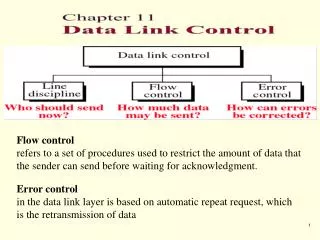
Flow control refers to a set of procedures used to restrict the amount of data that the sender can send before waiting for acknowledgment. Error control in the data link layer is based on automatic repeat request, which is the retransmission of data. Line discipline.

E N D
Flow control refers to a set of procedures used to restrict the amount of data that the sender can send before waiting for acknowledgment. Error control in the data link layer is based on automatic repeat request, which is the retransmission of data
Line discipline • It determines which device can send and when it can send. • It oversees the establishment of links and the right of a particular device to transmit at a given time.
Enquiry / Acknowledgment ENQ/ACK
ENQ/ACK • It is used in systems where there is no question of the wrong receiver getting the transmission • i.e. when there is a dedicated link between two devices so that the only device capable of receiving data is the intended one.
Poll / Select • It works with topologies where one device is designated as a primary station and the other devices are secondary stations and all are using a single transmission line. • All data communication must be made through the primary device • If the primary wants to receive data, it asks the secondaries if they have anything to send; this function is called polling. • If the primary wants to send data, it tells the target secondary to get ready to receive; this function is called selecting
Addresses • We need addressing for multipoint transmission. • Each secondary device has an address that differentiates it from the others. • If the transmission comes from the primary device, The address indicates the recipient of the data. • If the transmission comes from a secondary device, the address indicates the originator of the data.
Poll • It is used by the primary device to solicit transmissions from the secondary devices. • There are two possibilities for terminating the exchange • The secondary sends all its data and sends (EOT) frame • The primary “Time’s up”
Select • It is used whenever the primary device has something to send. • Any frame on the link is available to every device. • When a device recognizes its own address, it opens the frame and reads the data.
Flow control • It coordinates the amount of data that can be sent before • receiving acknowledgment. • It provides the receiver’s acknowledgment of frames • received corrupted.
Sliding Window Sender Sliding Window Receiver Sliding Window
Normal operation In Stop-and-Wait ARQ, numbering frames prevents the retaining of duplicate frames.
Figure 10-21 Lost ACK The McGraw-Hill Companies, Inc., 1998 WCB/McGraw-Hill
Figure 10-22 Selective Reject The McGraw-Hill Companies, Inc., 1998 WCB/McGraw-Hill
Data Link Protocols • Is a set of specifications used to implement the data link layer • Data link protocols differ by message delineation, frame length, and frame field structure. • Another fundamental difference is between asynchronous and synchronous transmission data link protocols.
Asynchronous Protocols • In asynchronous transmission (sometimes called start-stop transmission), each character is sent independently. • The transmission sequence begins with • a start bit • next the character is sent • then the parity bit • and finally a stop bit are sent. • The startbit is usually a 0 and the stop bit a 1. • Between transmissions (called “idle time”), a series of stop bits are sent. • When a new character is sent, the start bit is used by the receiver for synchronization.
Asynchronous Protocols • Protocols that belong to asynchronous protocols • XMODEM • YMODEM • ZMODEM • BLAST • Kermit
Synchronous Protocols • In synchronous transmission • data is sent in a large block called a frame • Synchronous transmission is used on both • point-to-point • multipoint circuits • In multipoint circuits, addressing information needs to be included in the frame. • Synchronous packets sometimes begin and end with a series of synchronization (SYN) characters that are used to help the receiver recognize incoming data.
Synchronous Protocols • Synchronous transmission protocols can be: • character-oriented: • Also known as byte-oriented protocols • Interpret a transmission frame as a succession of characters • bit-oriented: • Interpret a transmission frame as a succession of individual bits • Control information in a bit-oriented protocol can be one or multiple bits depending on the information embodied in the pattern
HDLC : High-level Data Link Control • It is a bit-oriented data link protocol • Designed to support both half duplex and full duplex communication over point-to-point and multipoint links. • It implements the ARQ mechanisms. • The HDLC protocol embeds information in a data frame that allows devices to control data flow and correct errors
HDLC : High-level Data Link Control • In 1979, the ISO made HDLC the standard as a Bit-oriented control protocol • The HDLC provides a transparent transmission (شفّاف) service at the data link layer of the OSI • The users of the HDLC service provides PDUs which are encapsulated to form data link layer frames. These frames are separated by HDLC "flags" and are modified by "zero bit insertion" to guarantee transparency
HDLC : High-level Data Link Control • Each piece of data is encapsulated in an HDLC frame by adding a trailer and a header. • The header contains an HDLC address and an HDLC control field. • The trailer is found at the end of the frame, and contains a (CRC) which detects any errors which may occur during transmission. • The frames are separated by HDLC flag sequences which are transmitted between each frame and whenever there is no data to be transmitted.
HDLC Frame Fields Flag field • is 8 bits of a fixed pattern (0111 1110). • There is one flag at the beginning and one at the end frame. • The ending flag of one Frame can be used as the beginning flag of the next frame. • To guarantee that the flag does not appear anywhere else in the frame • HDLC uses a process called Bit Stuffing. • Every time a sender wants to transmit a bit sequence having more than 6 consecutive 1’s, it inserts 1 redundant 0 after the 5th 1 Exceptions: • When the bit sequence is really a flag. • when transmission is being aborted. • when the channel is being put into idle.
Bit Stuffing • the process of adding one extra zero whenever there are 5 consecutive 1’s in the data, so that the receiver doesn’t mistake the data for a flag. A frame before bit stuffing: 01111110 01111100 101101111 110010 After 011111010 011111000 101101111 1010010
How does the receiver identify a stuffed bit? • Receiver reads incoming bits and counts 1’s. • When number of consecutive 1s after a zero is 5, it checks the next bit (7th bit). • If 7th bit = zero receiver recognizes it as a stuffed bit, discard it and resets the counter. • If the 7th bit = 1 then the receiver checks the 8th bit; If the 8th bit = 0, the sequence is recognized as a flag. 01111010 011111000 101101111 1010010
Address field • Address field is one byte or more • If the address is more than one byte, all bytes will end with 0,except the last one
Control Field • all three types contain a bit called (Poll/Final) P/F bit I-Frame • N(S) : sequence # of the sent frame • N(R) : sequence # of frame expected in return • N(R) is ACK field • If last frame received is error free N(R) number will be the next frame in sequence • If the frame was not received correctly N( R) number will be the number of damaged frame indicating the need for retransmission
Poll/Final • P/F = 1 POLL or Final • Poll if frame is sent by the primary • Final if frame is sent by the secondary
Information Field • Contains user data in I-frame and network management information in a U-frame. • It is possible to include flow and error control information in an I-frame that also contains data. • In 2-way exchange of data (1/2 or full-duplex), the 2nd station can ACK receipt of data from the 1st station in the control field of its own data frame rather than sending a separate frame just for ACK. • Combining data to be sent & ACK of the frame received in one single frame is called PIGGYBACKING.
Receive Ready (RR) • Positive ACK of a received I- frame • Receive Not Ready (RNR) • Is RR frame with additional duties • It Ack the receipt of a frame and announces that the receiver is busy • Reject (REJ) • This is a NAK frame that can be used in Go-back-n • Selective reject (SREJ) • This is a NAK frame used in Selective Repeat ARQ
Example • The figure shows an exchange using piggybacking where is no error • Station A begins the exchange of information with an I-frame numbered 0 followed by another I-frame numbered 1. • Station B piggybacks its acknowledgment of both frames onto an I-frame of its own. • Station B’s first I-frame is also numbered 0 [N(S) field] and contains a 2 in its N(R) field, acknowledging the receipt of A’s frames 1 and 0 and indicating that it expects frame 2 to arrive next. • Station B transmits its second and third I-frames (numbered 1 and 2) before accepting further frames from station A. • Its N(R) information, therefore, has not changed: B frames 1 and 2 indicate that station B is still expecting A frame 2 to arrive next.
Example • In the previous Example, suppose frame 1 sent from station B to station A has an error. • Station A informs station B to resend frames 1 and 2 (the system is using the Go-Back-N mechanism) • Station A sends a reject supervisory frame to announce the error in frame 1