Download
1 / 5
60 likes | 215 Views
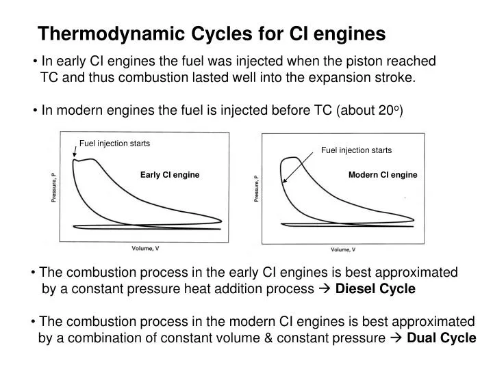
Thermodynamic Cycles for CI engines. In early CI engines the fuel was injected when the piston reached TC and thus combustion lasted well into the expansion stroke. In modern engines the fuel is injected before TC (about 20 o ). Fuel injection starts. Fuel injection starts.

E N D
Thermodynamic Cycles for CI engines • In early CI engines the fuel was injected when the piston reached TC and thus combustion lasted well into the expansion stroke. • In modern engines the fuel is injected before TC (about 20o) Fuel injection starts Fuel injection starts Early CI engine Modern CI engine • The combustion process in the early CI engines is best approximated by a constant pressure heat addition process Diesel Cycle • The combustion process in the modern CI engines is best approximated by a combination of constant volume & constant pressure Dual Cycle
Modern CI Engine Cycle vs Dual Cycle Fuel injected at 20o bTC A I R Air Combustion Products Actual Cycle Intake Stroke Compression Stroke Power Stroke Exhaust Stroke Qin Qin Qout Air Dual Cycle TC BC Const volume heat addition Process Compression Process Const pressure heat addition Process Expansion Process Const volume heat rejection Process
Dual Cycle Process 1 2 Isentropic compression Process 2 X Constant volume heat addition Process X 3 Constant pressure heat addition Process 3 4 Isentropic expansion Process 4 1 Constant volume heat rejection Qin 3 X 3 Qin 2 X 4 2 4 1 Qout 1
Thermal Efficiency For cold air-standard the above reduces to: where rc= v3/vX and a = P3/P2 Note, the Otto cycle (rc =1) and the Diesel cycle (a=1)are special cases:
The use of the Dual cycle requires information about either the fractions of constant volume and constant pressure heat addition (common assumption is to equally split the heat addition), or the maximum pressure P3. Transformation of rc and a into more natural variables yields For the same inlet conditions P1, V1 and the same compression ratio: For the same inlet conditions P1, V1 and the same peak pressure (actual design limitation in engines):