Download
1 / 65
930 likes | 2.74k Views
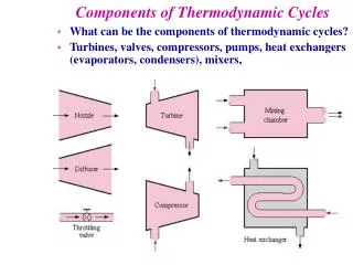
Components of Thermodynamic Cycles. What can be the components of thermodynamic cycles? Turbines, valves, compressors, pumps, heat exchangers (evaporators, condensers), mixers, . BUTTERFLY VALVE. GATE VALVE. SPHERE VALVE. PIPE CRACK. GLOBE VALVE. Throttling Devices (Valves).

E N D
Components of Thermodynamic Cycles • What can be the components of thermodynamic cycles? • Turbines, valves, compressors, pumps, heat exchangers (evaporators, condensers), mixers,
BUTTERFLY VALVE GATE VALVE SPHERE VALVE PIPE CRACK GLOBE VALVE
Throttling Devices (Valves) Typical assumptions for throttling devices • No work • Potential energy changes are zero • Kinetic energy changes are usually small • Heat transfer is usually small • Two port device
Look at energy equation: Apply assumptions from previous page: 0 0 0 0 We obtain: or Does the fluid temperature: increase, decrease, or remain constant as it goes through an adiabatic valve?
h const. T P const. h const. s Look at implications:If the fluid is liquid/vapor: • During throttling process: • The pressure drops, • The temperature drops, • Enthalpy is constant
Look at implications:if fluid is an ideal gas: Cp is always a positive number, thus:
P1 > P2 P S T T v v s Pressão Entalpia Temperatura En. Interna Entropia diminui constante gás ideal h=h(T), portanto T fica constante gás ideal u=u(T), portanto u fica constante diminui, Ds = Cpln(T2/T1)-Rln(P2/P1)
15MPa 611K (340oC) T (K) 373K (100oC) s, kJ/(kgK)
Cold embrittlement (dureza e rigidez mas baixa resistência a tensão) T-1000 (Robert Patrick)
Consequences of the Temperature Drop on Material Strenght Cold embrittlement (dureza e rigidez mas baixa resistência a tensão) Low temperature embrittlement does affect most materials more or less pronounced. It causes overloaded components to fracture spontaneously rather than accommodating the stress by plastic deformation. The picture shows a fractured fitting whose material was not suitable for low temperatures.
Refrigerant 12 enters a valve as a saturated liquid at 0.9607 Mpa and leaves at 0.1826 MPa. What is the quality and the temperature of the refrigerant at the exit of the valve? TEAMPLAY State (1) Liquid saturated, x=0 Psat = 0.9607 MPa Tsat = ? Hliq = ? State (2) Liq+vap x=? Psat = 0.1826 MPa Tsat = ? Hliq = ? 0.33 40oC -15oC 75kJ/kg 22 & 180 kJ/kg
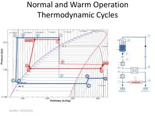
Throttling • Isentropic compression (1 to 2) • Constant pressure condensation (2 to 3) • Isenthalpic expansion (3 to 4) • Constant pressure evaporation (4 to 1) P-h Diagram of an Ideal Vapor-Compression Refrigeration Cycle The refrigerant enters the compressor as a saturated vapor and is cooled to the saturated liquid state in the condenser. It is then throttled to the evaporator and vaporizes as it absorbs heat from the refrigerated space.
Heat exchangers are used in a variety of industries • Automotive - radiator • Refrigeration - evaporators/condensers • Power production - boilers/condensers • Power electronics - heat sinks • Chemical/petroleum industry- mixing processes
Heat Exchangers • Now, we must deal with multiple inlets and outlets: If we have steady flow, then:
Heat Exchangers 0 0 0, (sometimes negligible) 0, (usually negligible) 0, (sometimes negligible) 0, (usually negligible)
Heat Exchangers • And we are left with The energy change of fluid A is equal to the negative of the energy change in fluid B.
SC mw = ? kg/s hw = 100 kJ/kg mvap = 0.1 kg/s hvap = 2776 kJ/kg mc = ? kg/s hc = 200 kJ/kg Resp.: mw = 2.576 kg/s
V2, P2 V1, P1 V2, P2 V1, P1 Nozzles and Diffusers • Nozzle--a device which accelerates a fluid as the pressure is decreased. • Diffuser--a device which decelerates a fluid and increases the pressure. These configuration is for sub-sonic flow.
For supersonic flow, the shape of the nozzle is reversed. Nozzles
General shapes of nozzles and diffusers nozzle diffuser Subsonic flow nozzle diffuser Supersonic flow
0 0 0 conservation of energy q = 0 (adiabatic) w = 0 (these are not work producing devices; neither is work done on them)
INLET T1 = 300C P1 = 100 kPa V1 = 250 m/s = 7 kg/s Diffuser Sample Problem An adiabatic diffuser is employed to reduce the velocity of a stream of air from 250 m/s to 35 m/s. The inlet pressure is 100 kPa and the inlet temperature is 300°C. Determine the required outlet area in cm2 if the mass flow rate is 7 kg/s and the final pressure is 167 kPa. OUTLET P2 = 167 kPa V2 = 35 m/s A2=?
solve for A2 Conservation of Mass: Steady State Regime But we don’t know v2! Remember ideal gas equation of state? and We know T1 and P1, so v1 is simple. We know P2, but what about T2? NEED ENERGY EQUATION!!!!
Energy Eqn If we assumed constant specific heats, we could get T2 directly The ideal gas law: And the area:
Vapor Power Cycles • We’ll look specifically at the Rankine cycle, which is a vapor power cycle. • It is the primary electrical producing cycle in the world. • The cycle can use a variety of fuels.
T Carnot Vapor Cycle compressor and turbine must handle two phase flows! TH < TC TH 1 2 4 TL 3 s • The Carnot cycle is not a suitable model for vapor power cycles because it cannot be approximated in practice.
Ideal power plant cycle is called the Rankine Cycle • The model cycle for vapor power cycles is the Rankine cycle which is composed of four internally reversible processes: • 1-2 reversible adiabatic (isentropic) compression in the pump • 2-3 constant pressure heat addition in the boiler. • 3-4 reversible adiabatic (isentropic) expansion through turbine • 4-1 constant pressure heat rejection in the condenser
Ideal power plant cycle is called the Rankine Cycle • The model cycle for vapor power cycles is the Rankine cycle which is composed of four internally reversible processes: • 1-2 reversible adiabatic (isentropic) compression in the pump • 2-3 constant pressure heat addition in the boiler. • 3-4 reversible adiabatic (isentropic) expansion through turbine • 4-1 constant pressure heat rejection in the condenser
What are the main parameters we want to describe the cycle? Net Power Net Specific Work Efficiency or
Start our analysis with the pump The pump is adiabatic, with no kinetic or potential energy changes. The work per unit mass is:
Boiler is the next component Boilers do no work. In boilers, heat is added to the working fluid, so the heat transfer term is already positive. So,
Proceeding to the Turbine Turbines are almost always adiabatic. In addition, we’ll usually ignore kinetic and potential energy changes:
Last component is the Condenser Condensers do no work (they are heat exchangers), and if there is no KE and PE,
P = 15 MPa P = 0.01 MPa A Rankine cycle has an exhaust pressure from the turbine of 0.1 bars. Determine the quality of the steam leaving the turbine and the thermal efficiency of the cycle which has turbine inlet pressure of 150 bars and 600C. Start an analysis: Assumptions: • Pump and turbine are isentropic; • P2 = P3 = 150 bars = 15 MPa • T3 = 600C • P4 = P1 = 0.1 bars = 0.01 MPa • Kinetic and potential energy changes are negligible
Put together property data • Pump (1 to 2) -> isoentropic (const. volume) • Boiler [heat exchanger] (2 to 3) -> const. pressure • Turbine (3 to 4) -> isoentropic • Condenser [heat-exchanger] (4 to 1) -> const. pressure
P = 15 MPa P = 0.01 MPa Property Data
P = 15 MPa P = 0.01 MPa Let start with pump work
More calculations... Enthalpy at pump outlet: Plugging in some numbers:
How Can I Get The Pump Outlet Temp? If the Enthalpy at pump outlet is 206.93 KJ/kg, then consider the compressedliquid a the same temperature of the saturated liquid which has h = 206.93 KJ/kg Interpolating from the saturated steam table one finds: 49oC
P = 15 MPa P = 0.01 MPa Calculate heat input
P = 15 MPa P = 0.01 MPa Turbine work Isentropic: Turbine work: