BIOPOTENTIAL AMPLIFIERS
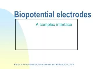
BIOPOTENTIAL AMPLIFIERS. By: Engr. Hinesh Kumar Lecturer. Biopotential Amplifier. Amplifiers used to process biopotentials are called biopotential amplifier. Biopotential Signals (e.g., ECG, EMG, EEG, EOG, … etc .)

BIOPOTENTIAL AMPLIFIERS
E N D
Presentation Transcript
BIOPOTENTIAL AMPLIFIERS By: Engr. Hinesh Kumar Lecturer
Biopotential Amplifier • Amplifiers used to process biopotentials are called biopotential amplifier. • Biopotential Signals (e.g., ECG, EMG, EEG, EOG, … etc.) • The basic function of biopotential amplifier is to increase the amplitude of a weak electric signal of biological origin. • Biopotential amplifiers typically process voltages, but in some cases they also process currents. • The frequency response of typical bioelectric amplifiers may be from dc (or near dc, i.e., 0.05 Hz) up to 100 kHz.
Cont… • Some biopotential amplifiers are ac-coupled, while some are dc-coupled. • The dc-coupling is required where input signals are clearly dc or changes very slowly. • At frequencies as low as 0.05Hz, the ac-coupling should be used instead of dc-coupling. • This is to overcome the electrode offset potential. • Also, the skin-electrode interface generates dc offsets. • The gain of biopotential amplifiers can be low, medium or high (x10, x100, x1000, x10000).
Low Gain Biopotential Amplifier • Gain factors x1 and x10. • The unity-gain amplifier is mainly for isolation, buffering and possibly impedance transformation between signal source and readout device. • Used for measurement of action potentials and other relatively high-amplitude bioelectric events.
Medium Gain Biopotential Amplifier • Gain factors x100 and x1000. • Used for recording of ECG waveforms and muscles potentials (EMG), etc.
High Gain Biopotential Amplifier • Gain factors over x1000. • Used in very sensitive measurement such as recording of brain potentials (EEG).
Typical Biopotential Amplifier Requirements The basic requirements that a biopotential amplifier has to satisfy are: • Biopotential amplifiers should have high input impedance i.e., greater than 10 MΩ. • Safety: the amplifier should protect the organism being studied. • Careful design to prevent macro and micro shocks. • Isolation and protection circuitry to limit the current through the electrode to safe level. • Output impedance of the amplifier should be low to drive any external load with minimal distortion
Cont… • Gain of the amplifier is greater than x1000 as biopotentials are typically less than a millivolt. • Most biopotential amplifiers are differential amplifier as signals are recorded using a bipolar electrodes which are symmetrically located. • High Common Mode Rejection Ratio (CMMR): biopotentials ride on a large offset signals or noise. • Rapid calibration of the amplifier in laboratory conditions. • Adjustable Gains: • Often the change in scale is automatic • Therefore calibration of the equipment is very important
Cont…. • The physiological process to be monitored should not be influenced in any way by the amplifier. • The measured signal should not be distorted. • The amplifier should provide the best possible separation of signal and interferences. • The amplifier has to offer protection of the patient from any hazard of electrical shock. • The amplifier itself has to be protected against damages that might result from high input voltages as they occur during the application of defibrillators or electrosurgical instrumentation
Operational Amplifier Circuit Model of Operational Amplifier
Operational Amplifiers Dual Power Supply Configuration for Operational Amplifiers
Operational Amplifiers Dual Power Supply Connections for Operational Amplifiers
Operational Amplifiers Typical Signal Voltage Sources for Operational Amplifiers
Operational Amplifiers • There are many circuit configurations using op amps as the active device, but only three basic classes of voltage amplifiers exist: • Inverting Amplifier • Non-inverting Amplifier • Unity Gain Non-inverting Amplifier
Inverting Amplifier • Inverting amplifier consists of an op-amp, an input resistor (R1), and a feedback resistor (R2). • The noninvertinginput is grounded in this circuit. • The point A, the junction of the two resistors and the operational amplifier's inverting input, is properly called the summing junction, or summation node.
Cont… Derivation
Cont… • The quantity R2/R1 gives us the magnitude of the voltage gain for this amplifier configuration, and the minus sign tells us that a 180-deeree phase inversion takes place. The voltage amplification or gain expression is represented by the symbol Av • The equation is also frequently seen in two alternative but equivalent form.
Example • Calculate the gain of an inverting amplifier if the feedback resistor (i,e., R2) is 120 kΩ. and the input resistor (R1) is 5.6 kΩ • Solution Av= -R2/R1 Av= -(120 kΩ / 5.6 kΩ) Av= 21
Non-inverting Amplifier • In the non-inverting amplifier input voltage is applied directly to the non inverting input terminal of the operational amplifier . • Feedback resistor R2, and input resistor R1, are the same as in the inverting follower, except that the other end of R1, is grounded.
Cont… Derivation
Example • Calculate the voltage gain of a “non-inverting amplifier if R2, = 10 kΩand R1, = 2.2 kΩ. Solution At high gains, the gains of the inverting and non-inverting amplifier are very nearly equal but, at low gains, a difference is noted.
Unity Gain Non-inverting Amplifier • In the unity Gain non-inverting amplifier the resistor network is not used in this circuit, and the output is connected directly to the inverting input, resulting in 100%. Av= R2/R1+1 Av= 0+1 Av= 1
Multiple Input Circuits • More than one input network may be used in an op-amp network, and the output voltage represents the summation of the respective input currents. • Three input networks are used in this circuit, and there are three input sources: E1, through E3.
Example • Find the output voltage in a circuit, such as one in fig, if R1, = R2, = R3, = 10 k Ω, R4 = 22 kΩ, E1, = 100 mV, E2, = 500 mV, and E3, = 75 mV. Solution:
Differential Amplifier • A differential amplifier produces an output voltage that is proportional to the difference between the voltage applied to the two input terminals. • The voltage gain for the differential signals is the same as for the inverting followers, provided the ratio equality of R2/R1 = R4/R3 is maintained. • Differential amplifiers are useful because it rejects common voltages while amplifying the differential signal of interest.
Instrumentation Amplifier • This circuit uses three operational amplifiers, A1, through A3,. • The two input amplifiers (i.e., A1, and A2,) are connected in the non-inverting amplifier configuration, while the third amplifier is connected in the simple dc differential amplifier. • Simplify circuit analysis by setting the gain of A3, equal to unity (i.e.. R4, = R5, = R6, = R7,). • let us assume E1, is applied to the non-inverting input of amplifier A1, and that E2, is applied to the non-inverting input of amplifier A2. • Additionally, E3 is the output of A2,, and E4 is the output of A1,. • Voltages E1, and E2 are also shown at the inverting inputs of A1 and A2.
Cont…. There are two contributing sources to E3, and E4. In the case of E3: If we set R2=R3
Cont….. • The gain of instrumentation Amplifier is