Differential Amplifiers
Differential Amplifiers. Outline. Single-Ended Versus Differential Operation. The transitions disturb the differential by equal amounts, leaving the difference in tact. Immunity to Supply Noise. If VDD changes by ∆V, Vout changes by the same amount. Noise in VDD affects VX and VY,


Differential Amplifiers
E N D
Presentation Transcript
Single-Ended Versus Differential Operation The transitions disturb the differential by equal amounts, leaving the difference in tact.
Immunity to Supply Noise If VDD changes by ∆V, Vout changes by the same amount. Noise in VDD affects VX and VY, but not Vx-Vy
Reduction of Coupled Noise Noise coupled from L3 to L1 and L2 to L1 cancel each other.
Sensitivity to the Common mode level Excessive low Vin,CM turns off Devices.
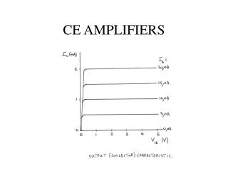
Input/Output Characteristics Minimum Slope Independent of Vin,cm Maximum Slope Thus maximum Gain
Range of Vin,cm Lower bound of Vin,cm: VP should be sufficiently high in order for M3 to act as a current source. Upper bound of Vin, cm M1 and M2 need to remain in saturation.
Sensitivity to Vin, cm M3 in the linear region is modeled as a resistor M1=M2 =On M1=M2 =Off M1=M2 =On M1=M2 =On M1=M2 =Off M1=M2 =Off M3=Linear M3=Linear M3=Linear
Maximum Allowable Output Swing The higher the input CM level, the smaller the allowable output swings.
Transconductance ∆Vin1Represents the maximum differential signal a differential pair can handle.
Linearity W/L increases ISS Constant Constant W/L ISS increases
Determinations of Small Signal Gain • CS with resistive source degeneration • Thevenin Resistance • Cascode • Superposition Principle
CS with resistive source degeneration Interpretation: The resistance at the drain Divided by the resistance in the source path
Treat M1 as a CS stage with resistive source degeneration to find VX/Vin
Replace M1 by its Thevenin Equivalent Circuit If RS is sufficiently large, then the small signal gain of the amplifier can be obtained using thevenin’s equivalent circuit (see hand out)
Conversion of Arbitrary inputs to Differential and Common-Mode Components
Simulation Vin,m=1 mV Vout,m=8.735 mV Av=-8.735 Calculations: Gm=1mS ro=30.53 KOhm RL=12 Kohm Av=-Gm(ro||RL)=-8.615
Common-Mode Response • Sensitivity of Vout,CM due to Vin,CM • In the presence of resistor mismatch • In the presence of transistor mismatch • Common Mood Rejection Ratio (CMRR)
Sensitivity of Vout,CM due to Vin,CM Vin,CM ↑, VP↑, I(RSS)↑,VX,V↓
Output CM Sensitivity due to Vin, CM Vout,m =0.285 mV Vin,cm =1 mV RL=12 K Gm=1.043 mS Gds3=58.29 uS Av, CM(Analytical)=0.343 Av, CM(Simulation)=0.285 (Excluding gmb, ro)
Common-Mode to Differential Conversion at High Frequencies Even if the output resistance of the current source is high, the common-mode to differential conversion becomes significant at high frequencies.
Resistor Mismatch (from CS with resistive source degeneration)
Voutp-Voutn Differential Mode signal at the output: 1.176 uV
Effect of CM Noise in the Presence of Resistor Mismatch Common Mode to Differential Conversion
Diode Connected Load Problem: Difficult to decrease (W/L)P without dropping the common mode voltage of Vout.
Addition of Current Source to Increase Voltage Gain Reduce gm by reducing current rather than the aspect ratio. Reduce I(M3) and I(M4).