PIV Experiment for Flow Mapping in Lungs
170 likes | 304 Views
Kristin Roberts (Project Manager, ME) Morgan DeLuca (ME) Ryan Mark (ME) Jimmy Moore (CE) Brad Demarest ( EE) Jake Snider (IE) Michael Antoniades (Faculty Guide). PIV Experiment for Flow Mapping in Lungs. P13051. Final Project Review - P13051. Agenda. Project Description

PIV Experiment for Flow Mapping in Lungs
E N D
Presentation Transcript
Kristin Roberts (Project Manager, ME) Morgan DeLuca (ME) Ryan Mark (ME) Jimmy Moore (CE) Brad Demarest (EE) Jake Snider (IE) Michael Antoniades (Faculty Guide) PIV Experiment for Flow Mapping in Lungs P13051 Final Project Review - P13051
Agenda • Project Description • Customer needs and specifications • Selected Concepts • Final Design • Final Product • Testing Results • Schedule • Budget • Project Status • Objective Project Evaluations
Project Description • The Army Medical Research Lab needs to validate their CFD models for healthy and diseased lungs • RIT will perform particle image velocimetry (PIV) on lung models to validate the CFD • Our senior design team designed and developed a testing apparatus that can be used for PIV testing • Project sponsored by MSD and Dr. Robinson
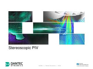
What is PIV? • Used for flow visualization and velocity measurements • Fluid is seeded with tiny tracer particles • The particles are illuminated using a laser sheet, and a camera takes pictures of the particles • Fluid velocity profiles can be obtained by analyzing particle movement from frame to frame
Customer Needs • Create model of a hollow lung using specified geometry up to the 14th generation. • Obtain flow field profiles using particle image velocimetry. • Obtain velocity field maps at 10 locations for 5 planes at each location. • Validate computational flow model. • Accommodate various image locations. • Simulate inhalation and exhalation at steady state. • Control flow at each airway outlet to mimic the boundary conditions of the computational model. • Monitor flow rate and pressure. • Accommodate imaging with no distortion. • Create Labview program to run experiment. • Write a procedure for the experiment. • Locate same image positions • Can switch between two models
Specifications • Model Reynolds number must be within 12% of desired Reynolds number • Must match indexes of refraction within ±0.02 (not currently implemented) • Model can be rotated from 0 to 45 degrees • Camera can be moved in X, Y, and Z directions • Must be able to locate the same point within 5mm • Models can be switched in no longer than a couple days • Tank must not show any signs of leakage in a 24 hour period • Model and connections must not show any signs of leakage while running at 32 gpm (only tested with small flow rates) • Pump can reach flow rates in the range of 6-32 gpm • Measure pressure within 5% of physical value • System components can withstand pressures consistent with the proposed flow rates * Specifications without check marks have not been tested due to scope reduction and budget constraints
Final Design 2 • Major Components: • Laser • Tank • Camera Positioning System • Needle Valve • Through Wall Manifold • Pressure Sensor System • Pump • Reservoir • Gathering Manifold • DAQ • Computer Setup • Ball Joint 12 1 3 11 4 5 6 10 7 8 9
Final Product • This represents the current system that was able to be built with the exception of the pump • Currently have smaller pump to simulate function • Computer will be needed with Labview installed for future tests (personal laptop was used for validation)
Testing Results • Known pressures were applied to sensors • Yielded linear output voltage curve • Makes predictability trivial and error minimal • There are some resistances is system • Cause lower voltage to be read by Labview • Can correct for resistance because it will remain constant
Schedule • Still waiting on gear pump which has limited testing • Project construction fell about 1.5 weeks behind schedule when waiting for additional budget approval • Were able to use down time to get ahead of schedule on documentation • Final system (including documentation) was completed on schedule
Budget • Spent $4,645 (including pump which has not arrived) • Current prototype cost $2,203 • Initially estimated full system as $11,400 • Will cost about $7,365 to update to full system (using 81 pressure sensors) • Will cost about $3,484 to update to a valveing system (4 outlets per pressure sensor)
Project Status All major components of the system are working • System has only been tested with water at low flow rates • Labview is reading pressure values consistent with Fluke calibration • Valves can successfully be used to change pressure at outlets • Complete system runs with no leaks • Still have not recieved gear pump from Viking • Camera can be positioned precisely
Objective Project Evaluation Successes: • Pump system w/ manifold functions with placeholder model and temporary pump. • Valving system allows for verifiable pressure adjustment. • LabVIEW program and pressure sensing subsystem are functional. • Successful integration of subsystems using proof-of-concept system.
Objective Project Evaluation (Cont.) Setbacks: • The ball joint attachment to the tank lid is temporary at best. • Cannot adequately test repeatability/consistency of pressure sensors with only two sensors. • A rack and pinion would be useful for precise vertical adjustment of camera positioning. • The gear pump was ordered too late and did not arrive in time to adequately test.
Suggestions for Future Work • Fabricate the 81-outlet model and use that instead of the temporary model. • Employ a more permanent/reliable model positioning system. • Update the 81-outlet LabVIEW code • Test pump to ensure functionality • Acquire accurate power supply