Download
1 / 30
300 likes | 521 Views
Task 6: Short Period Nb 3 Sn Superconducting Helical Undulator. Jim Clarke & George Ellwood 24/4/12. Task 6 Objectives. Increase the magnetic field of an undulator by using Nb 3 Sn Increased positron yield -> more efficient Create & test a short prototype (~300mm)

E N D
Task 6: Short Period Nb3Sn Superconducting Helical Undulator Jim Clarke & George Ellwood 24/4/12
Task 6 Objectives • Increase the magnetic field of an undulator by using Nb3Sn • Increased positron yield -> more efficient • Create & test a short prototype (~300mm) • Design iterated to make (~500 mm) Nb3Sn module with maximum field / shortest period possible • Comparison with existing NbTi magnet
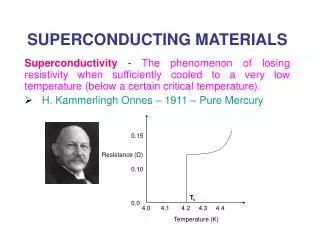
NbTi Helical Undulator • Final Parameters: • 215A • Beam tube ID: 4.7 mm • Winding ID: 6.35 mm • Field on axis: 0.86 T • Margin with this conductor: 30%
NbTi Cryomodule • A 4m module containing 2 x 1.75m helical undulators (11.5 mm period) has been constructed • Closed loop cryo system with cryocooler (4.2K LHe bath)
NbTi Cryomodule • Argonne have proposed that the 4m module be tested with electron beam on the APS linac test line (~400 MeV) • Logical next step for testing cryomodule/undulator performance • We are currently assessing packaging and transportation costs
Nb3Sn Conductor Size • What wire diameters fit in existing 3.25 mm groove? 0.5 bare (0.65 insulated) 0.6 bare (0.75 insulated) 0.4 bare (0.55 insulated) Square packing 3.3 mm wide PF = 42 % Square packing 3.25 mm wide PF = 46 % Square packing 3.0 mm wide PF = 50 % Hex packing 3.3 mm wide PF = 43 % Hex packing 3.25 mm wide PF = 48 % Hex packing 3.0 mm wide PF = 49 %
Nb3Sn Conductor Choice • Nb3Sn Availability • Oxford Superconducting Technology (OST) • Supercon Inc. • Nb3Sn Performance • Due to small winding area, need large currents to achieve ~1 T on axis • Need to know critical current in winding at ~4 T • No companies have data for performance below 9 T • Large extrapolation needed – no confidence
Performance of candidate wires Based on extrapolation to low fields the OST E2004 wire was chosen due to it’s higher expected performance.
Supercon -alternative wire choice • Field on axis 1.2T 40%> NbTi • Operating current 720A • Peak field on conductor 3.5T
Supercon Test Results from CERN • Operating current 720A required • Magnet may quench as some parts are in <1T field • However, we should be able to learn something by winding an undulator with this wire • So, we will buy 1km and wind two 300mm helical undulators and measure there performance
Cryostat There are two identical cryostats that are suitable for testing the undulator.
Top plate The top plate design will be based on that used previously for the helical undulator but adapted to fit the cryostat. The top plate will fit either of the two cryostats. On the top plate a stepper motor manipulation system is included that enables a hall probe to be driven through the bore of the magnet to create field maps.
Ground plane coating of former • Zircotecin UK have plasma sprayed alumina onto a test former. • Results appear to be excellent • Good, uniform coverage • High breakdown voltage • Only issue appears to be that it is a little rough so could potentially damage glass fibre braid
Vacuum impregnation requirements In the undulator there are two separate regions that need to be filled. The region around the helix which is packed with conductor and glass. The region around the winding pins which is very open. With the NbTi helical undulators the winding pin region was prefilled with particles and then the undulator was vacuum impregnated with epoxy resin. It was difficult to add enough filler to this volume and it required using a vibrating table.
Resin System 1 • Investigate using a resin system from a family developed for the ITER Toroidal Field coil case insertion. • This is a resin that incorporates a high volume % of filler but has a low enough viscosity to be able to be used in vacuum impregnation. • The thermal contraction of the resin/filler should be similar to that of stainless steel.
Resin System 2 • The resin used will be 60/40 Atlas mix. • This is an excellent low temperature resin with a low viscosity and long pot life. • The filler will be either dolomite or woollastonite. • There are still some questions regarding using this resin/filler system.
Resin System The gap between the top of the winding and the top of the winding groove is ~0.5mm. Will the resin be able to travel along this path?
Flow testing mould A small test mould has been created together with an insert. The gap between the insert and the mould is 0.5mm all round.
Flow Trials • The Atlas resin flow trials have shown that resin/filler mix should be able to flow along the narrow gap along the undulator. • The modelling overestimates the speed of the resin, but the model can be adapted to represent the experiment. • More realistic geometry can then be modelled.
Full impregnation Even if the resin/filler can flow along the small gap at the top of the winding groove, We need to be sure that the resin will penetrate and fully impregnate at the base of the groove. In order to do this if the flow trials is successful we will impregnate the undulator created in the winding trial and then section to check the impregnation.
Experiment A small sample with 5 layers of wire was created. This was vacuum impregnated with the resin/filler mix
Microscopy After sectioning it could be seen that the glass fibre on the conductor filtered the dolomite filler, but the epoxy resin was able to penetrate and fully encapsulate the winding.
Next steps Using a dummy undulator test the impregnation tooling with the resin/filler mix.
Task Summary • Supercon wire tests suggest we should be able to fabricate a useful prototype • Winding trials have shown that a viable ground plane insulation has been found • We will now build 2 x 300mm identical prototypes to fulfil the requirements of the contract – agreed with WP leaders at RAL March 2012