Image Quantitation in Microarray Analysis
Explore the process of microarray analysis, from array construction to data visualization using fluorescence signals. Learn about experimental design, image quantitation, and software packages available. Understand the importance of normalization and quality control for accurate results.
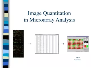

Image Quantitation in Microarray Analysis
E N D
Presentation Transcript
Image Quantitationin Microarray Analysis Moretomorrow...
Microarray analysis • Array construction, hybridisation, scanning • Quantitation of fluorescence signals • Data visualisation • Meta-analysis (clustering) • More visualisation
pseudo-colourimage sample(labelled) probe (on chip) Technical [image from Jeremy Buhler]
Experimental design • Track what’s on the chip • which spot corresponds to which gene • Duplicate experimental spots • reproducibility • Controls • DNAs spotted on glass • positive probe (induced or repressed) • negative probe (bacterial genes on human chip) • oligos on glass or synthesised on chip (Affymetrix) • point mutants (hybridisation plus/minus)
Images from scanner • Resolution • standard 10m [currently, max 5m] • 100m spot on chip = 10 pixels in diameter • Image format • TIFF (tagged image file format) • can be compressed • (eg. Lempel-Ziv-Welch: ~ 5x compression) • 1cm x 1cm image at 16 bit = 2Mb (uncompressed) • other formats exist eg. SCN (used at Stanford University) • Separate image for each fluorescent sample • channel 1, channel 2, etc.
Images in analysis software • Typical experiment: • “normal” state, Cy3-labelled sample (green) • “perturbed” state, Cy5-labelled sample (red) • hybridisation, then scanning • overlay images pseudo-colour image • qualitative representation of results Image spot colour Signal strength Gene expression • yellow: normal = perturbed unchanged • green: normal > perturbed repressed • red: normal < perturbed induced
Quantitation process (1) Accurate representation of signal for each spotand determine ratio channel1:channel2 • Determine spot boundary • construct grid (dimensions of array / spot size) • iterative process to find spots • Measure signal • fluorescence • 8 bit = 256 shades • 16 bit = 65’536 shades • absolute output values vary from system to system
Quantitation process (2) • Measure background • local (usually best) • selected region • selected spots / probes from different species • Quality control • eg. fraction of pixels greater than background (ScanAlyze) • flag aberrant spots • Determine ratio of signal strengths for each spotCh1/Ch2 = (Ch1I-Ch1B)/Ch2I-Ch2B)
Normalisation • Eliminate systematic variation • correct for • dye incorporation • print-tip effects • hybridisation efficiencies • etc. • How? • Use STATISTICS!
Normalisation references [statistics] Normalization for cDNAmicroarray data Yang et al. (2001) In preparation Statistical methods for identifyingdifferentially expressed genes in replicatedcDNA microarray experiments Dudoit et al. (2000) Technical report #578 Berkeley Statistics Dept. both available fromftp://ftp.ch.embnet.org/pub/MAcourse/material/
Quantitation - problems • Reference signal is close zero • channels ratio (Ch1/Ch2) tends to infinity • Non-uniform background • “mean” background sometimes non-representative • bright particles • streaks on image • safer to use “median” (middle value) • less contribution by extreme values
Quantitation à la ScanAlyze signal background
ScanAlyze output CH1I ch1 intensity CH2I ch2 intensity SPIX number of pixels in spot CH1B median intensity of the local background (recommended) CH2B median intensity of the local background (recommended) CH1BA mean intensity of the local background CH2BA mean intensity of the local background BGPIX number of background pixels Thus to calculate channel ratios: Ch1 CH1I - CH1B --- = ----------- Ch2 CH2I - CH2B Quality control: CH1GTB1 fraction of pixels in spot greater than background (CH1B) CH2GTB1 fraction of pixels in spot greater than background (CH2B) CH1GTB2 fraction of pixels in spot greater than 1.5 X background (CH1B) CH2GTB2 fraction of pixels in spot greater than 1.5 X background (CH2B) CH1EDGEA mean magnitude of the horizontal and vertical Sobel edge vectors within spot 1 CH2EDGEA mean magnitude of the horizontal and vertical Sobel edge vectors within spot 2
Software packages - quantitation • ScanAlyze • by Michael Eisen (Stanford University) • quantitation of images • no data visualisation • free from http://rana.lbl.gov/ • ImaGene • BioDiscovery Inc. • quantitation and some data visualisation • demo from http://www.biodiscovery.com/ • plus many others - explore!
Making sense of raw data • Difficult to see results in tabulated data • Represent in graphical form Data visualisationexamples from ImaGene . . .
ScanAlyze quick demo