Download

1 / 11
110 likes | 275 Views
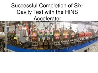
Successful Completion of Six-Cavity Test with the HINS Accelerator. Six-Cavity Beam Line. HINS six-cavity beam line constructed on the east side of MDB. Beam line can test concept of driving multiple cavities with a single RF amplifier.

E N D
Successful Completion of Six-Cavity Test with the HINS Accelerator
Six-Cavity Beam Line • HINS six-cavity beam line constructed on the east side of MDB. • Beam line can test concept of driving multiple cavities with a single RF amplifier. • Significant cost savings may be realized by using fewer RF power amplifiers.
Vector (I/Q) Modulator: Modulates phase and amplitude independently: With = (2 - 3)/2 = (2 + 3)/2 Output power ~ cos2() Output phase ~ water load circulator Four Port Hybrid Input → 2 1 2 Phase Shifters Output :← to circulator and cavity 3 3 4
LLRF System Setup • RF Feedback on RFQ amplitude and phase • Feed forward learning correction of Ferrite Vector Modulators
Cavity Probe Signals • RFQ RF Feedback ON • FVM Control OFF • Beam ON (7 mA) Magnitude (MV) Phase (degrees) Beam Off at 300 us *Buncher 1, Cavity 2, and Cavity 3 were detuned so that the FVM’s have enough dynamic range to compensate disturbances.
Cavity Probe Signals • RFQ RF Feedback ON • FVM Control ON • Beam ON (7 mA) Magnitude (MV) Phase (degrees) *Cavity 1 FVM correction did not completely converge due to limited dynamic range of FVM
RFQ Magnitude and Phase Regulation • RFQ RF Feedback ON • FVM Control ON • Beam ON RFQ Magnitude RFQ Phase +/-1% Pulse to Pulse Average of RMS Error (50 Pulses) Pulse to Pulse Average of RMS phase Error = 0.0147 degrees Pulse to Pulse Average of RMS magnitude Error = 0.0207%
Beam Energy Stability • Difference between green and red trace show time-of-flight between diagnostic line BPMs. • Energy scale is ~1.4keV/degree for time of flight BPM measure-ments. Plot shows noise level of about 10keV for 3MeV beam.
Contributors • AD • HowiePfeffer • GeorgeKrafczyk • Mike Kucera • Brad Claypool • Jim Patrick • AndreyPetrov • Bill Marsh • Charlie Briegel • Dennis Nicklaus • Denise Finstrom • Carl Schumann • Stan Johnson • Todd Johnson • Aisha Ibrahim • Roger Tokarek • Duane Voy • Nathan Eddy • Peter Prieto • Andrea Saewert • Lionel Prost • AD • Bob Webber • Jim Steimel • Bruce Hanna • Vic Scarpine • Alex Chen • Bruce Popper • Maurice Ball • AbhishekDeshpande • Dave Peterson • Ralph Pasquinelli • Elmie Evans-Peoples • Wai-Ming Tam • Brian Chase • JulienBranlard • Paul Joireman • Ed Cullerton • Vitale Tupikov • Philip Varghese • Chris Jensen • Kevin Martin • Steve Hays • APC • Robyn Madrack • Dave Wildman • HenrykPiekarz • Jean-Paul Carneiro • Al Moretti • Nikolai Mokhov • TD • Giorgio Apollinari • Gennady Romanov • TimergaliKhabiboulline • IouriTerechkine • Leonardo Ristori • Tom Page • Tom Nicol