Download
1 / 33
330 likes | 352 Views
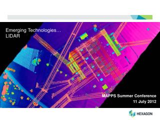
Learn about LIDAR, a state-of-the-art technology used for aerial laser surveying, its capabilities, accuracy, and post-processing applications.

E N D
LIght Detection And Ranging (LIDAR) It’s Uses and Capabilities State of Alaska DOT/PF Design Meeting #11 Tuesday, June 14th, 2005 8:30AM Presented By: Robert T. Thomason Jr. LIDAR Production Manager AeroMap U.S. [An AERO-METRIC Inc. Company]
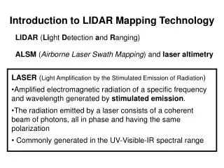
Airborne Laser Surveying “State of the Art” • Differential Global Positioning System (DGPS) provides horizontal location of the LIDAR Sensor. • Inertial Measurement Unit (IMU) provides orientation of the LIDAR sensor. • Laser scanning determines the distance to Earth’s surface by measuring the time in flight of each laser pulse.
Light Detection & Ranging (LIDAR) “The Basics” • Operated from plane or helicopter. • LIDAR system emits laser pulses which travel to the surface where they are reflected back to the aircraft. • Determines the distance to Earth’s surface by measuring the time in flight (based on the speed of light) for each laser pulse.
MULTIPLE RETURNS • The Laser footprint is 20 cm to 45 cm in diameter depending on the aircraft elevation and the beam size selection. • AeroMap’s 30/70 system records the first, second, third and last return. • In this example the first three returns are from the tree and a portion of the laser beam finds it’s way to the ground for the last return. • Must have a “Nano-second” mentality. 1st 2nd 3rd Last
LIDAR Sensor System • Installed in AeroMap’s twin-engine Cessna 320 • Optech’s ALTM LIDAR system, Model 30/70 • 70-kilohertz (capable of measuring 70,000 points per second)
Can produce: Elevation data to 15 cm or better at 200 - 1,200 meters; 35 cm at 3,000 meters Relative accuracy between measurements 3-7 cm Horizontal accuracy 0.1-meters to 1.5-meters depending on flying height & differential GPS Different systems have different accuracy specifications LIDAR Accuracy
Fully automatic method of directly measuring height or elevation of terrain from an airborne platform Penetrates between foliation to the ground Does not need sunlight (it’s own light source at 1064nm) or a particular sun angle, as does Photogrammetric methods Able to measure ground surface as well as trees, bushes, buildings, and power lines Low cost compared to ground or photogrammetric surveys with equal requirements Reduced production schedule Timely, easy to deploy, able to obtain data quickly in remote areas Why LIDAR?
Post-Processing • Integration with REALM & TerraSolid (TerraScan/TerraMatch) • View and process data in multiple projections • Stereo Images from Intensity Data – breakline generation • Visualization (QT Modeler, & Arc9 GIS LAS Module & “Hill-Shade”) AeroMap Workstation
LIDAR Project Layout Classified Bare-earth Data Classified Bare-earth Data (Intensity) Bare-earth Shaded Relief To Palmer To Anchorage
Initial 4-Return (w/Intensity) LIDAR DatasetNo Bare Earth Classification Intensity Image Cross-Section View Glenn Highway AK Rail Road NAD83 UTM (AeroMap In-House Default Datum)
“Bare-earth” (Ground) Classification Passive Algorithm 98% Classified TerraScan - Microstation View Ortho-metric View (Bare-earth Data Only Viewed) Cross-section View Not Classified (In Yellow) Due to Elevation Angle (More than 6 Degrees) Not Classified (Empty Area) Newly Classified (Bare-earth) Data Passive Algorithm Run on Dataset
“Bare-earth” (Ground) Classification Aggressive Algorithm 98% Classified TerraScan - Microstation View Ortho-metric View Cross-section View (Bare-earth Data Only Viewed) Fully Classified (Yellow Data Gone) 7 Degrees Input Bare-earth Classified Data (Full Tile)
LIDAR “Classes” Defined • 1st Return- Green • 2nd Return- White • 3rd Return- Purple • 4th Return (Last Return)- Yellow • Buildings- Cyan • Bare-Earth- Red Peters Creek Drainage ½m Cross-Section
Aggressive Algorithms Errors Hiland Road Bridge TerraScan Cross-section View Showing Area that needs to be Manually Re-Classified Bare-earth Model (QT-Modeler) Showing Misclassified Bridge
QA/QC “Blunder” IdentificationBirds and Other Anomalies Skagway, Alaska (1st Return Dataset) Ortho-Metric Perspective View Cruise Ship Cruise Ship Vertical Anomalies
QA/QC “Blunder” Identification Atmospheric Anomalies Skagway, Alaska Ortho-metric View Cross-section View Suspected Anomalies inDataset Inverse View
Handwritten Field Books Pictorial Digital Analog PPK (Post-Processed Kinematic) GPS Data Aircraft IMU Acquisition (System Check) Vehicle Profiles (System and Classification Check) Solo Fieldwork (Classification Field Check) Terrascan “Control Output Report” John’s Hopkin’s University “QT-Modeler” LIDAR Quality Assurance & Quality Control (QA/QC)
Digital elevation models (DEM) CAD Packages Digital 3-D modeling Earthworks modeling, profiles, volumes, contours etc. DEM for orthophotos & image drapes Floodplain mapping Airport Obstruction Surveys Value Added LIDAR Products:
LIDAR Value Added Products AutoCAD Land Desktop 4 3D Faces TIN & DEM Generation and Editing 2000m Square tile (4.2 Million Points) 149MB AutoCAD File 3D Faces “Zoomed In”
PRODUCTS: Contours One-foot contours for floodplain mapping McCarthy, Alaska
Digital Contours From LIDAR DEM (1/2-meter posting) PRODUCTS: These are ½-meter contours with LIDAR “point cloud” in white - Homer Spit, Alaska
Digital Orthophotos from LIDAR DEM Value Added Products: McCarthy, AK
PRODUCTS: Intensity Image CoastalErosion Study for COE • 1064 nm band near-infrared • Gray scale based on returned signal amplitude • Optech 30/70 provides intensity with each of the four returns Homer, Alaska
Distance to project site & size / cost sharing Helicopter/Fixed-wing Delivery schedule Absolute accuracy (application) Flying height/swath width Number & placements of GPS base stations Deliverables Point cloud (unclassified / classified) ASCII, DEM, ArcInfo GRID, TIN, Gridded “Lattice” files, etc. Continuous contours / custom contour sheets Watershed, slope and aspect maps Perspective views, fly-through movies, etc. Primary Cost Factors
Project size & complexity Fly today – deliver tomorrow Depends on products Ground Quality Assurance and Quality Control survey checks completed Establish the H & V datum prior to flight NAD 83, UTM, Zone 4, Ellipsoidal Heights, Meters Standard datum is faster Special processing needs Unusual formats Develop software It can all be done it just takes time Schedule Factors
LIDAR is the future of mapping: “Beam me up Scotty” Accuracy Vertical = 15 cm to 35 cm Horizontal = 0.1-meter to 2.5 meters 1/2000 of the flying height Fast Data may produce many products Cost effective LIDAR Summary
Anchorage Hilton Hotel “Point Cloud” QUESTIONS ? Websites of interest: www.lidaralaska.com Information on LIDAR in Alaska www.appliedimagery.com Excellent “free” point cloud viewer www.airbornelasermapping.com Loads of LIDAR information Image courtesy of AeroMap U.S.
Contact Information: Robert T. Thomason Jr. LIDAR Production Manager ASPRS Certified Photogrammetrist R#812 AeroMap U. S. 2014 Merrill Field Drive Anchorage, Alaska 99501 907.272.4495 E-mail: thomason@aeromap.com Please Call or E-mail if you have ANY additional questions