Download
1 / 20
220 likes | 404 Views
Mechanical Measurement and Instrumentation MECN 4600. Professor: Dr. Omar E. Meza Castillo omeza@bayamon.inter.edu http://www.bc.inter.edu/facultad/omeza Department of Mechanical Engineering Inter American University of Puerto Rico Bayamon Campus. Tentative Lecture Schedule.

E N D
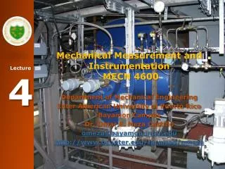
Mechanical Measurement and Instrumentation MECN 4600 Professor: Dr. Omar E. Meza Castillo omeza@bayamon.inter.edu http://www.bc.inter.edu/facultad/omeza Department of Mechanical Engineering Inter American University of Puerto Rico Bayamon Campus
Topic 6: Measurement of Temperature Thermocouple
Course Objectives • To measure temperature using a thermocouple.
Temperature • Temperature is the most common used and measured variable. Actually, the definition of temperature and scale is not well understood. • Temperature is described as the property of an object that describes its hotness and coldness. • The zeroth law of thermodynamics states that two systems in thermal equilibrium with a third system are in thermal equilibrium with each other. • The conversion equations for the four modern temperature scales are: • oC = 5/9 (oF - 32) oF = 9/5 oC + 32 • K = oC + 273.15 oR = oF + 459.67
Temperature • Temperature can be measured via a diverse array of sensors. All of them infer temperature by sensing some change in a physical characteristic. Six types with which the engineer is likely to come into contact are: THERMOCOUPLES, RESISTIVE TEMPERATURE DEVICES (RTD and THERMISTORS), INFRARED RADIATORS, BIMETALLIC DEVICES, LIQUID EXPANSION DEVICES, AND CHANGE-OF-STATE DEVICES. • The most common method of measuring and controlling temperature uses an electrical circuit called a THERMOCOUPLE.
Temperature Thermocouple RTD Thermistor
Thermocouple • A thermocouple is a device based upon the findings of SEEBECK (1821) who showed that a small electric will flow in a circuit composed of two dissimilar conductors when their junctions are kept at different temperatures. The electromotive force (emf) produced under these conditions is known as the “Seebeck emf”. The pair of conductors that constitute the thermoelectric circuit is called THERMOCOUPLE. • The output of a thermocouple circuit is a voltage, and there is a definite relationship between this voltage, and temperatures of the junctions that make up the thermocouple circuit.
Copper T emf Constantan Thermocouple Thermocouple Circuit • To demonstrate the errors introduced in this procedure, introduced the junction of a type T thermocouple in boiling water (known to be at 100ºC) and read the voltage across the leads. The reading was 3.634 mV, which corresponds to 86.1ºC. Thermocouple Type T
Copper Probe junction T emf Copper Constantan Reference junction Ice bath Thermocouple • This temperature error arises because the connection of the thermocouple leads to the voltimeter constitutes two additional thermoelectric junctions that substract voltage from the signal being measured. • This problem can be remedied using the arrangement show in this figure:
Thermocouple • One thermocouple junction is held in an ice bath at 0ºC. This called THE REFERENCE JUNCTION. The other thermocouple junction is THE TEMPERATURE PROBE. If the probe is at 0ºC, then there is no thermoelectric voltage across the leads because the thermoelectric voltage created by each junction cancel each other out. • There are three basic phenomena that can occur in a thermocouple circuit: (1)Seebeck effect, (2)Peltier effect, and (3)Thomson effect. • SEEBECK EFFECT Thomas Johann Seebeck (1770-1831).The Seebeck effect refers to the generation of a voltage potential, or emf, in an open thermocouple circuit caused by a difference in temperature between junctions in the circuit.
Material A 2 T1 T2 1 Material B Material A emf Thermocouple • There is a fixed, reproducible relationship between the emf and the junction temperatures T1 and T2. • This relationship is expressed by the Seebeck coefficient, defined as:
Heat Transfer Material A Material B Current I emf (external) Thermocouple • PELTIER EFFECT Peltier Coefficient
q2 q1 T1 T2 i Voltage supply Thermocouple • THOMPSON EFFECT Thomson Coefficient
A A T3 T1 emf = 0 A A T2 Fundamental Thermocouple Laws • Law of Homogeneous Materials.- A thermoelectric current cannot be sustained in a circuit of a single homogeneous material by the application of heat alone, regardless of how it might vary in cross section.
T1 C A emf = 0 B C T1 Fundamental Thermocouple Laws • Law of Intermediate Materials.- The algebraic sum of the thermoelectric forces in a circuit composed of any number of dissimilar materials is zero if all of the circuit is at a uniform temperature. T1
Fundamental Thermocouple Laws • Law of Successive or Intermediate Temperatures.- If two dissimilar homogeneous materials produce thermal emf1 when the junctions are at T1 and T2 and produce thermal emf2 when the junctions are at T2 and T3, the emf generated when the junctions are at T1 and T3 will be emf1 + emf2. Copper Copper Copper T1 T2 T1 emf1+emf2 emf2 emf1 Constantan Constantan Constantan Copper Copper Copper T2 T3 T3
Laboratory 3 WebPage Omar E. Meza Castillo Ph.D.