Download
1 / 16
180 likes | 427 Views
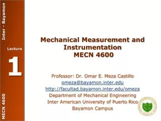
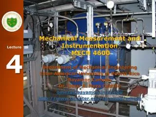
Mechanical Measurement and Instrumentation MECN 4600. Department of Mechanical Engineering Inter American University of Puerto Rico Bayamon Campus Dr. Omar E. Meza Castillo omeza@bayamon.inter.edu http://www.bc.inter.edu/facultad/omeza. Tentative Lecture Schedule. Topic 4: P&ID.

E N D
Mechanical Measurement and Instrumentation MECN 4600 Department of Mechanical Engineering Inter American University of Puerto Rico Bayamon Campus Dr. Omar E. Meza Castillo omeza@bayamon.inter.edu http://www.bc.inter.edu/facultad/omeza
Topic 4: P&ID Piping and Instrumentation Diagram
Course Objectives • To use P&ID in order to read engineering plans.
P&ID Piping and Instrumentation Diagram • A Piping and Instrumentation Diagram - P&ID, is a schematic illustration of functional relationship of piping, instrumentation and system equipment components. • The P&ID are used to operate the process system. • The P&ID shows the flows in a plant (in the chemical or process industry) and the corresponding sensors or actors. • At the same time, the P&ID gives a name ("tag") to each sensor and actor, along with additional parameters. • This tag identifies a "point" not only on the screens and controllers, but also on the objects in the field. • Many standards: ISA, DIN, etc
P&ID Piping and Instrumentation Diagram • A P&ID should include: • All process equipment identified by equipment number • All pipes identified by a line number. Pipe size and material of construction should be shown (material may include as a part of the identification number) • All valves with an identification number along with their type & size should be shown • Ancillary fittings that are part of piping system such as inline sight glasses, strainers and stream traps with an identification number. • Pumps identified by a suitable code number. • All control loops and instruments with identification
P&ID is equal that PFD • Process Flow Diagram (PFD) is a schematic illustration of the system. shows the relationships between the major components in the system.
P&ID and Symbols • Sets of symbols are used to depict mechanical equipment, piping, piping components, valves, equipment drivers and instrumentation and controls. These symbols are assembled on the drawing in a manner that clearly defines the process. The instrumentation and control (I&C) symbols used in P&IDs are generally based on ISA-5.1, Instrumentation Symbols and Identification. • The first letter of any tag name, therefore, will indicate the process variable being measured. The most common process variables in a process plant include: • F – Flow • L – Level • P – Pressure • T – Temperature
P&ID and Symbols • Typical Letter Combinations, a reprint of a page in ISA-5.16, shows many possible letter combinations and describes the device represented by the letters. Reading across Figure 2-10 (page 30 of pdf file P&ID and symbols), starting with an F, the initiating or measured variable for flow rate, the succeeding letters describe the devices and functions as follows: : • Letter Combination Description • FRC Flow Recorder Controller. A recorder for the value of instantaneous flow, integral with a flow controller. • FICFlow Indicating Controller. An instantaneous flow indicator combined with a flow controller.
Homework2 WebPage Due, Tuesday, February 05, 2013 Omar E. Meza Castillo Ph.D.