Download

1 / 14
140 likes | 323 Views
CFD-Experiments Integration in the Evaluation of Six Turbulence Models for Supersonic Ejectors Modeling. Y. Bartosiewicz , Z. Aidoun, P. Desevaux, and Y. Mercadier. Condenser. Generator. Evaporator. G. Generator. ECH. Qgen. C. D. Generator. evaporator. I. Qp. condenser. Qcond.

E N D
CFD-Experiments Integration in the Evaluation of Six Turbulence Models for Supersonic Ejectors Modeling Y. Bartosiewicz, Z. Aidoun, P. Desevaux, and Y. Mercadier
Condenser Generator Evaporator G Generator ECH Qgen C D Generator evaporator I Qp condenser Qcond Condenser Ejector Qev Evaporator Supersonic ejectors in refrigeration F E A Condenser B H
Main objectives of this study • Short term: • - Assess the ability of CFD to represent the operation range of a supersonic ejector in a simple case: single phase, known properties: Air • - Choose the best suited turbulence model among those giving reasonable results in comparison to the computational cost: • - k-epsilon • - Realizable k-epsilon • - RNG • - k-omega and k-omega-sst • - RSM • Correctly predict some local (shocks position…) and global (entrainment rate, pressure recovery) features • Long term: • - Have a better understanding of involved phenomena (local physics, that 1-D models cannot provide) • - Set up a reliable tool for geometrical design • - Use CFD to model ejector in refrigeration with refrigerants and two phase flow Boussinesq hypothesis
Numerical tools • - CFD package FLUENT: F.V. • - Roe flux splitting for inviscid fluxes • - Time marching technique (implicit Euler) • - Time preconditioning (for low Mach) • - Algebraic multigrid solver (block Gauss -Seidel) • Adaptative structured-unstructured mesh • - Standard (equilibrium) wall functions Adaptation following the pressure gradient, and y+ close to walls
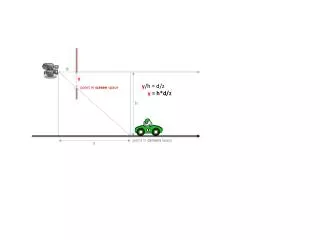
Flow Facility (IGE*) – Computational domain*: Institute of Applied Energy, CREST-CNRS, Belfort, France m2 = 0 or constant Computational domain • -Axisymetric computational domain • Equivalent cross section for the secondary flow
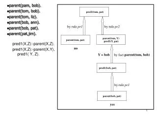
Static pressure hole . P 1 P 2 Capillary tube Measurements (IGE): the centerline pressure Flow physics Outlet - Probe with 1 mm external diameter - Hole diameter = 0.3 mm - Pressure transducer
Comparison with experiments:Centerline pressure: without probe modeling(No secondary flow) None of the turbulence models is able to completely reproduce shock reflections in terms of: - Phase - Strength However the average pressure recovery is properly modeled. P1 = 5 atm m2 = 0. kg/s
Centerline Pressure: with probe modeling(No secondary flow) P1 = 5 atm m2 = 0. kg/s • - The probe has a significant effect even though its size is small • The numerical results are all improved with the probe modeling • The RNG model gives the best results among k-epsilon based models and RSM • The most important discrepancy is observed in expansions (35-50%) (condensation) • In compressions, it is about 10%
Comparison between RNG and k-omega models(No secondary flow) - The standard k-omega model overpredicts shocks downstream the fourth shock - RNG and k-omega-sst results comparable - Both models give the same pressure recovery value further downstream (not shown) P1 = 5 atm m2 = 0. kg/s
Other operation conditions P1 = 4 atm P1 = 6 atm m2 = 0. kg/s
Measurements (IGE): the non-mixing length Laser Tomography * Power:1.5 kW in the blue line * Fmirror = 300 Hz * Light sheet with parallel edges (thickness = 0.3 mm) * Natural marker: water droplets issued from condensation (diameter = 0.1 m) * Additional markers: 1 m oil droplets
Supersonic ejector operating with a secondary flow: Non-mixing length The laser tomography picture is treated by an image processing software to deduce lm (Desevaux et al.) Passive scalar equation Ideal colorant: lm m2 = 0.028 kg/s
Concluding remarks • * Ejector with zero secondary flow: • RNG and k-omega-sst models provide good and comparable results. • More discrepancies in expansions (condensation?) • * CFD-experiments integration: CFD revealed that intrusive measurement systems should be included in models for supersonic flows • *Preliminary tests conducted with induced flow have shown that the k-omega-sst model accounts best for the mixing A wide range of operating conditions needs to be modeled with induced flow: non-shocked to shocked ejector +More realistic boundary conditions at the secondary inlet: total pressure To check: - entrainment ratio: m2/m1 - local profiles To ascertain the selection of the k-omega-sst model