Download
1 / 13
130 likes | 338 Views
Design and Implementation of VLSI Systems (EN1600) Lecture 22: Sequential Circuit Design (1/2). Prof. Sherief Reda Division of Engineering, Brown University Spring 2008. [sources: Weste/Addison Wesley – Rabaey/Pearson]. Purpose of time: we need time to order events. Sequential circuits.

E N D
Design and Implementation of VLSI Systems (EN1600) Lecture 22: Sequential Circuit Design (1/2) Prof. Sherief Reda Division of Engineering, Brown University Spring 2008 [sources: Weste/Addison Wesley – Rabaey/Pearson]
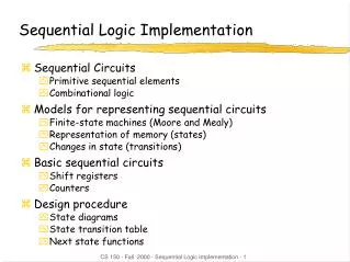
Purpose of time: we need time to order events Sequential circuits • Combinational logic • output depends on current inputs • Sequential logic • events are ordered using the clock signal • output depends on current and previous inputs • memory elements are used to store the results of the events or states (certainly if they will be used in the future).
Differences between latches and flipflops • Latches are level sensitive • Flipflops are edge triggered
Pass Transistor Latch Pros + Tiny + Low clock load Cons Vt drop nonrestoring output noise sensitivity dynamic diffusion input 1. Latch Design • Pass Transistor Latch • Pros • + • + • Cons
Transmission gate + - 1. Latch Design • Transmission gate • + No Vt drop • - Requires inverted clock • Inverting buffer • + • + Fixes either • Inverting buffer • + Restoring • + Fixes either • Output noise sensitivity • Or diffusion input • Inverted output
Tristate feedback + 1. Latch Design • Tristate feedback • + Static • Output noise sensitivity • Diffusion input • Static latches are now essential • Buffered input • + Fixes diffusion input • + Noninverting • - Output noise sensitivity
1. Latch Design • Buffered output • + Output noise sensitivity eliminated • Widely used in standard cells • + Very robust (most important) • Rather large • Rather slow (1.5 – 2 FO4 delays) • High clock loading • Datapath latch • + Smaller, faster • - unbuffered input
Flip-flop is built as pair of back-to-back latches 2. Flip-flop design
Enable: ignore clock when en = 0 Mux: increase latch D-Q delay Clock Gating: increase in setup time, skew 2. Latch/Flip-flop with ENABLE
Set forces output high when enabled Flip-flop with asynchronous set and reset 2. Latch/Flip-flop with SET/RESET [Figure from Baker]
Setup and hold times CLK Register t D Q t t su hold D DATA CLK STABLE t t c q 2 Q DATA STABLE t • Setup time: the minimum time that the data input must be valid before clock transition • Hold time: the minimum time that the data input must be valid after the clock transition