Download
1 / 33
330 likes | 561 Views
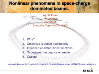
Magnetism from Conductors and Enhanced Nonlinear Phenomena. IEEE TRANSACTIONS ON MICROWAVE THEORY AND TECHNIQUES, VOL. 47, NO. 11, NOVEMBER 1999 J. B. Pendry , A. J. Holden, D. J. Robbins, and W. J. Stewart. Professor: Ming- Shyan Wang Student: Lin Chao Yuan Stust -student number:4992C081.

E N D
Magnetism from Conductors and Enhanced Nonlinear Phenomena IEEE TRANSACTIONS ON MICROWAVE THEORY AND TECHNIQUES, VOL. 47, NO. 11, NOVEMBER 1999 J. B. Pendry, A. J. Holden, D. J. Robbins, and W. J. Stewart • Professor:Ming-ShyanWang • Student: Lin Chao Yuan • Stust-student number:4992C081
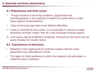
I. INTRODUCTIONII. DEFINING AN EFFECTIVE PERMEABILITYIII. EXAMPLES OF MAGNETIC MICROSTRUCTURESIV. AN ISOTROPIC MAGNETIC MATERIALV. ENHANCED NONLINEAR EFFECTS
Abstract We show that microstructures built from nonmag-netic conducting sheets exhibit an effective magnetic permeability μeff occurring materials, including large imaginary components ofμeff . The microstructure is on a scale much less than the wave-length of radiation, is not resolved by incident microwaves, and uses a very low density of metal so that structures can be extremely ightweight . Most of the structures are resonant due to internal capacitance and inductance, and resonant enhancement combined with ompression of electrical energy into a very small volume greatly enhances the energy density at critical locations in the structure, easily by factors of a million and possibly by much more. Weakly nonlinear materials placed at these critical locations will show greatly enhanced effects raising the possibility of manufacturing active structures whose properties can be switched at will between many states.
INTRODUCTION (1/2) IN A SENSE, every material is a composite, even if the individual ingredients consist of atoms and molecules. The original objective in defining a permittivity ε , and permeability μ was to present an homogeneous view of the electromagnetic properties of a medium. Therefore, it is only a small step to replace the atoms of the original concept with structure on a larger scale. We shall consider periodic structures defined by a unit cell of characteristic dimensions α The contents of the cell will define the effective response of the system as a whole. Clearly, there must be some restrictions on the dimensions of the cell. If we are concerned about the response of the sys- tem to electromagnetic radiation of frequency ω , the conditions are easy to define as follows:
INTRODUCTION (2/2) If this condition were not obeyed, there would be the possibility that internal structure of the medium could diffract as well as refract radiation giving the game away immediately. Long wavelength radiation is too myopic to detect internal structure and, in this limit, an effective permittivity and permeability is a valid concept. In Section II, we shall discuss how the microstructure can be related to εeff ,μeff. We show first how to calculate μeff for a system, then we propose some model structures that have magnetic activity and give some numbers for these systems. Finally, we show how electrostatic energy can be strongly concentrated in these structures and, hence, demonstrate the potential for enhancing nonlinear effects.
DEFINING AN EFFECTIVE PERMEABILITY(1/4) We are seeking to build structures with effective epsilon and μ as follows: where we assume that the structure is on a scale much shorter than the wavelength of any radiation so that we can sensibly Fig. 1. Unit cell of a periodic structure. We assume that the unit cell dimensions are much smaller that the wavelength of radiation, and average over local variations of the fields. In the case of the B-field, we average over the faces of the cell and in the case of the H-field, over one of the edges. speak of an average value for all the fields. A key question is “how do the averages differ?” Clearly, if the structure is made of thin wires or sheets of metal, then if the averages were taken over the same regions of space εeff ,μeff. would always be unity. However, we observe that Maxwell’s equations. may be applied in the integral form
DEFINING AN EFFECTIVE PERMEABILITY(2/4) This form of the equations immediately suggests a prescrip-tion for averaging the fields. For simplicity, we shall assume that the periodic structure is described by a unit cell whose axes are orthogonal, as shown in Fig. 1. Some of the arguments used in this section are similar to those we used in deriving a finite-difference model of Maxwell’s equations. We choose to define the components of Have by averaging the H-filed along each of the three axes of the unit cell. If we assume a simple cubic system
DEFINING AN EFFECTIVE PERMEABILITY(3/4) There is only one caveat concerning the definition of the unit cell: its edges must not intersect with any of the structures contained within the unit cell. This leaves us free to cut the structure into a whole number of unit cells when we come to create a surface and nsures that the parallel component of Have is continuous across the surface as required in a consistent theory of an effective medium. To defineBave, we average the B-Filed over each of the three faces of the unit cell, defined as follows:
DEFINING AN EFFECTIVE PERMEABILITY(4/4) Fig. 2. Model A consists of a square array of metallic cylinders designed to have magnetic properties in the direction parallel to the axes of the cylinders. Thus, if we seek a large effect, we must try to create fields that are as inhomogeneous as possible. We shall explore various configurations of thin sheets of metal, derive μeff and discuss the results with a view to making the effect as large as possible.
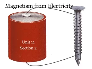
EXAMPLES OF MAGNETIC MICROSTRUCTURES(1/7) We start with a very simple structure for the purposes of illustration, i.e., “model A” shown in Fig. 2. Let us apply an external field H0 , which we shall take to be parallel to the cylinders. We assume that the cylinders have a conducting surface so that a current j per unit length flows. The field inside the cylinders is
EXAMPLES OF MAGNETIC MICROSTRUCTURES(2/7) where the second term on the right-hand side is the field caused directly by the current, and the third term is the result of the depolarizing fields with sources at the remote ends of the cylinders. If the cylinders are very long, the depolarizing field will be uniformly spread over the unit cell, but will have the same number of lines of force in it as the direct field inside the cylinders. We now calculate the total electromotive force (emf) around the circumference of a cylinder as follows: where σ is the resistance of the cylinder surface per unit area. The net emf must balance and, therefore,
EXAMPLES OF MAGNETIC MICROSTRUCTURES(3/7) over the entire unit cell is However, if we average the H-field over a line lying entirely outside the cylinders Hence, we define
EXAMPLES OF MAGNETIC MICROSTRUCTURES(4/7) For an infinitely conducting cylinder or in the high fre-quency limit, μeff is reduced by the ratio of the cylinder volume to the cell volume. This ratio of volumes will turn out to be the key factor in determining the strength of the effect in all our models. Evidently, in the present model, μeff can never be less than zero or greater than unity. It should also be mentioned that to maximize the effect, we could have replaced the metallic cylinders with prisms of square cross section to maximize the volume enclosed within the prism. If the resistivity of the sheets is high, then the additional contribution to μeff is imaginary, but always less than unity.
EXAMPLES OF MAGNETIC MICROSTRUCTURES(5/7) A further point that should be noted is that all the structures we discuss have electrical as well as magnetic properties. Fig. 3. Mode B consists of a square array of cylinders as for model A , but with the difference that the cylinders now have internal structure. The sheets are divided into a “split ring” structure and separated from each other by a distance D. In any one sheet, there is a gap that prevents current from flowing around that ring.
EXAMPLES OF MAGNETIC MICROSTRUCTURES(6/7) Fig. 4. When a magnetic field parallel to the cylinder is switched on it induces currents in the “split rings,” as shown here. The greater the capacitance between the sheets, the greater the current. this particular case, we can crudely estimate for electric fieldsperpendicular to the cylinders.
EXAMPLES OF MAGNETIC MICROSTRUCTURES(7/7) where F is the fraction of the structure not internal to a cylinder. In deriving , we assume that the cylinder is a perfect conductor and neglect depolarizing fields arising from interaction between cylinders. Inclusion of εeff in our calculations removes one difficulty by ensuring that Evidently, without εeff the velocity of light in the effective medium would have exceeded that in free space. Most of the structures discussed in this paper have a similar εeff .
AN ISOTROPIC MAGNETIC MATERIAL(1/9) The structures shown above give magnetic properties when the field is aligned along the axes of the cylinders, but have essentially zero magnetic response in other directions. They suffer from another potential problem: if the alternate polarization is considered where the electric field is not parallel to the cylinders, the system responds like an effective metal because current is free to flow along the length of the cylinders. For some applications, this highly anisotropic behavior may be undesirable. Therefore, we redesign the system with a view to restoring isotropy and minimizing purely electrical effects.
AN ISOTROPIC MAGNETIC MATERIAL(2/9) To this end, we need a basic unit that is more easily packed into arrays than is a cylinder and that avoids the continuous electrical path provided by a metal cylinder. We propose an adaptation of the “split ring” structure, in which the cylinder is replaced by a series of flat disks each of which retains the “split ring” configuration, but in slightly modified form . First, we shall calculate the properties of disks stacked in a square array, as shown if Fig. 13. This structure is still anisotropic, a problem we shall address in a moment, but by eliminating the continuous conducting path that the cylinders provided, it eliminates most of the electrical activity along this direction.
AN ISOTROPIC MAGNETIC MATERIAL(3/9) The two-dimensional square array can be made by printing with metallic inks. If each printed sheet is then fixed to a solid block of inert material with thickness α , the blocks can be stacked to give columns of rings. This would establish magnetic activity along the direction of stacking, i.e., the Z-axis. How do we make a symmetrical structure? Start from the structure just described, comprising successive layers of rings . Plain view of a split ring structure in a square array
AN ISOTROPIC MAGNETIC MATERIAL(4/9) Fig. 7. Building 3-D symmetry: each successive restacking of the structure adds a ring to another side of the unit cell. stacked along the Z-axis. Next, cut up the structure into a series of slabs thickness α , make incisions in the Y-Z-plane, and be careful to avoid slicing through any of the rings. Each of the new slabs contains a layer of rings, but now each ring is perpendicular to the plane of the slab and is embedded within. Print onto the surface of each slab another layer of rings and stack the slabs back together again. The unit cell of this second structure is shown in the middle of Fig. 14.
AN ISOTROPIC MAGNETIC MATERIAL(5/9) In the next step, a third set of slabs is produced by cutting in the X-Z-plane, printing on the surface of the slabs, and reassembling. Finally, we now have a structure with cubic symmetry whose unit cell is shown in the right-hand side of Fig. 7. plane, printing on the surface of the slabs, and reassembling. Finally, we now have a structure with cubic symmetry whose unit cell is shown in the right-hand side of Fig. 7. Under these conditions, we can calculate the capacitance between unit length of two parallel sections of the metallic strips.
AN ISOTROPIC MAGNETIC MATERIAL(6/9) Fig. 8. Plot of μeff for the cubic split ring structure calculated using the chosen parameters. (a) For copper rings σ1=200.(b) For more resistive rings, σ1=2000.
AN ISOTROPIC MAGNETIC MATERIAL(7/9) The effective magnetic permeability we calculate, on the assumption that the rings are sufficiently close together and that the magnetic lines of force are due to currents in the stacked rings, are essentially the same as those in a continuous cylinder. This can only be true if the radius of the rings is of the same order as the unit cell side. We arrive at
AN ISOTROPIC MAGNETIC MATERIAL(8/9) where σ1 is the resistance of unit length of the sheets measured around the circumference. To give some examples, let us choose a convenient set of parameters. These parameters do not quite satisfy all the inequalities, which is difficult to do with reasonable numbers, but note that the inequalities are only important to the accuracy of our formulas, not to the functioning of the structure. The resonant frequency at which μeff diverges is given by
AN ISOTROPIC MAGNETIC MATERIAL(9/9) If we choose to manufacture the split rings from a layer of copper, it is easily possible to achieve σ1=200. Evidently, from Fig. 8, this produces a highly resonant structure. In order to see a substantial effect, we have to increase the resistance either by increasing the resistivity of the material of which the rings are made or by making them thinner. The scaling of frequency with size can be deduced from, in which we see that the resonant frequency scales uniformly with size: if we double the size of all elements in a given structure, the resonant frequency halves. Nearly all the critical properties are determined by this frequency.
ENHANCED NONLINEAR EFFECTS(1/5) We have seen how the addition of capacitance to the struc-ture gives a far richer variety of magnetic behavior. Typically, this happens through a resonant interaction between the natural inductance of the structure and the capacitative elements and, at the resonant frequency, electromagnetic energy is shared between the magnetic fields and the electrostatic fields within the capacitative structure. To put this more explicitly, take the split ring structure described in Figs. 5 and 5, most of the electrostatic energy of the capacitor is located in the tiny gap between the rings. Concentrating most of the electromagnetic energy in this very small volume will results in an enormously enhanced energy density.
ENHANCED NONLINEAR EFFECTS(2/5) If we wish to enhance the nonlinear behavior of a given compound, we locate a small amount of the substance in the gap where the strong electrostatic fields are located. Since the response scales as the cube of the field amplitude, we can expect enhancements of the order of the energy density enhancement squared. Furthermore, not only does the structure enhance the nonlinearity, it does so in a manner that is very economical with the material: less that 1% of the structure need be filled with the nonlinear substance.
ENHANCED NONLINEAR EFFECTS(3/5) Fig. 9. The emf acting around one of the sheets of the split ring in Fig. 12 as a function of the distance δ around the ring. Vin denotes the emf on the inner ring, and Vout that on the outer ring. Note that this ring is cut at δ=0, so that the emf is discontinuous.
ENHANCED NONLINEAR EFFECTS(4/5) We shall now calculate the energy density in the capacitance between the two split rings in Figs. 5 and 6. First, we calculate the voltage between the two rings as a function of the incident magnetic field H0 The electric field between the two halves of the ring is shown in Fig. 9 and is of the order. into
ENHANCED NONLINEAR EFFECTS(5/5) We now argue that the electrostatic energy density in the incident electromagnetic field is equal to the magnetic energy density, which, in turn, can be related to the electrostatic energy density in the ring. Hence: If we evaluate this formula on resonance, we get a much simplified formula as follows:
Conclusion In conclusion, we have shown how to design structures made from nonmagnetic thin sheets of metal, which respond to microwave radiation as if they had an effective magnetic permeability. A wide range of permeabilties can be achieved by varying the parameters of the structures. Since the active ingredient in the structure, the metal film, comprises a very small fraction of the volume
References • http://translate.google.com.hk/ • http://120.117.16.3:2266/stamp/stamp.jsp?tp=&arnumber=798002 • http://a2z.fhl.net/bible/greek/Gclass1.html
Thank you for listening and viewing I hope you can accept and love 2014/04/08