Download

1 / 56
560 likes | 582 Views
Cardiac ultrasound is advancing to 3D imaging, but image analysis lags. Explore a Kalman filtering framework for real-time 3D segmentation with deformable models.

E N D
Real-time segmentation of 3D echocardiograms,using a state estimation approach with deformable models Fredrik Orderud Norwegian University of Science & Technology
Outline • Background and motivation • Framework description • Publications • Ellipsoid model (computers in cardiology, 2006) • Spline model (MICCAI, 2007) • Active-shape model (CAIP, 2007) • Subdivision models (CVPR, 2008) • Speckle-tracking (f-MICCAI, 2008) • Edge + speckle-tracking (IUS, 2008) • Coupled segmentation (IUS, 2008) • Automatic alignment (SPIE, 2009) • Conclusions
Cardiac ultrasound is moving from 2D to 3D Latest generation of scanners are capable of acquiring dense image volumes in real-time Important competitive advantage to MR & CT Image analysis is lagging behind Only post-processing tools are currently available We want analysis tools robust and fast enough to operate during imaging Ultrasound background
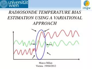
Left ventricle • One of four heart chambers. • Pumps oxygenated blood from lungs to the rest of the body. • The most clinically interesting heart chamber. (c) 2006, Wikipedia
Image segmentation: Problem of labeling image data with information about boundaries, structure locations etc. Difficult problem, especially in ultrasound. Clutter, reverberation, angle dependency and drop-out disrupts images, and makes segmentation difficult. Example: How to handle that part of the cardiac wall is missing? Approach: Use a geometric model to assist the segmentation process Ultrasound segmentation
Common types of 3D models • Level sets • Implicit surface: Zero-crossing of finite diff quantification (Malladi, PAMI 1995) • PDE-based update scheme to evolve surface • Discrete model • Flat polygonal surface, e.g. simplex mesh (Delingette, IJCV 199) • Iterative force-based update scheme • Statistical shape model • Discrete surface, with predefined deformation modes (Cootes, IPMI 1993) • Iterative displacement-based update scheme • Can be extended to also capture texture and motion pattern - AAMM (Bosch, TMI 2002) • Parametric surface • Continuous surface description (FEM, spline, subdivision etc.) • Typ. iterative gradient descent update scheme Iterative update schemes
Kalman segmentation background • Prof. Andrew Blake & al., univ. Oxford, 1990’ies • Kalman filter to update a spline contour • Noniterative least-squares fitting [1] Blake A, Curwen R, Zisserman A. A framework for spatiotemporal control in the tracking of visual contours. International Journal of Computer Vision 1993;11(2):127–145. [2] Blake A, Isard M, Reynard D. Learning to track the visual motion of contours. Artificial Intelligence 1995;78(1- 2):179–212. [3] Blake A, Isard M. Active Contours. Secaucus, NJ, USA: Springer-Verlag New York, Inc., 1998. ISBN 3540762175.
2D: G. Jacob, A. Noble (univ. Oxford): ASM model, updated by a Kalman filter Investigated relationship between shape variation and wall thickening to pathology. 2D: Siemens corporate research: Similar Kalman-filter algorithms Subspace-constrained deformations Anisotropic measurement error 3D: Q Duan, E. Angelini (Columbia univ.): Cubic spline surface, updated by “level-set” Mumford-Shah gradient descent. 33 ms processing time per frame Prior real-time cardiac work [4] Jacob G, Noble JA, Mulet-Parada M, Blake A. Evaluating a robust contour tracker on echocardiographic sequences. Medical Image Analysis 1999. [5] Jacob G, Noble JA, Kelion AD, Banning AP. Quantitative regional analysis of myocardial wall motion. Ultrasound in Medicine Biology 2001. [6] Jacob G, Noble JA, Behrenbruch CP, Kelion AD, Banning AP. A shape-space based approach to tracking myocardial borders and quantifying regional left ventricular function applied in echocardiography. IEEE Medical Imaging 2002 [7] D. Comaniciu, X.S. Zhou & al: Robust real-time myocardial border tracking for echocardiography: An information fusion approach, IEEE Medical imaging, 2004 [8] X.S. Zhou, A. Gupta, D. Comaniciu: An information fusion framework for robust shape tracking, IEEE Pattern analysis and machine intelligence, 2004 [9] Qi Duan, E. Angelini & al: Real-time segmentation of 4D ultrasound by Active Geometric Functions, IEEE Intl. Symposium on Biomedical Imaging (ISBI) 2008.
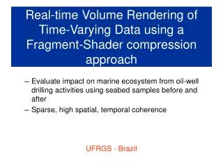
Kalman filter: • Invented in 1960 (R. Kalman). • Widely used for navigation and RADAR tracking. Kalman filtering has some limitations related to linearity and Gaussian assumptions. Is it out of date? Apollo guidance computers
Research goals • Extend Kalman tracking framework to 3D, and support: • Different types of deformable models. • Different imagemeasurement. • Multiple simultaneous models, arranged in a hierarchy. • Use the framework to measure aspects of left ventricular function: • Chamber volumes. • Myocardial muscle mass. • Regional myocardial strain.
Approach • Use deformable surface models • Described by a limited set of parameters • Combine with global transform for position, size and orientation • Treat tracking as a sequential state estimation problem • Multivariate normal distribution • Use a Kalman filter to predict and update state, based on image measurements and a kinematic model Tracking driven by propagation of uncertainty through time
Edge detection Attractors Kalman filter Speckle tracking Tracking framework Segmentations Kinematic prediction Deformable model(s) Volume curves Strain curves Confidence maps Anatomic landmarks Next frame Kinematic prediction
Predict Predict state, based on a kinematic model and previous estimates Model Evaluate surface points, based on state vector. Compute Jacobian matrices Measure Search for edges in surface normal direction, and/or Track speckle pattern. Assimilate Perform outlier rejection. Assimilate measurement in information space. Update Compute updated state estimate, based on prediction and measurements. Update surface model on screen. State-vector parameters: Local shape. Global pose (trans, rot, scale). Processing chain Bayesian least squares solution instead of iterative refinement
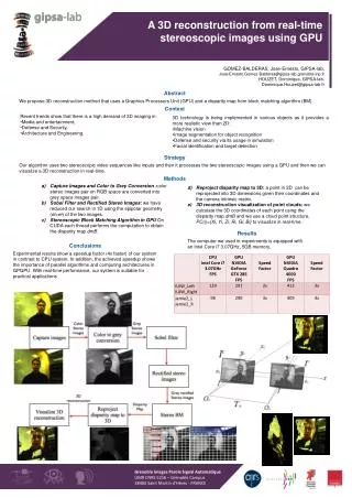
Extract intensity “profiles” in surface normal direction 1D edge-detection: “Transition criterion”, where the edge forms a transition from one intensity level to another Determine edge position that minimizes the sum of squared errors. Edge detection Green - edge discovered outside the surface Red - edge detected inside the surface Yellow - discarded outlier edge Black - discarded too weak edge
Block matching: Extract “kernel volumes” in myocardium Match to bigger “search volumes” in next the frame Search for best integer displacement (SAD). Sub-sample refinement (optical flow). Speckle tracking Green - displacement vectors Red - discarded displacement vectors (weak or outside sector) Yellow - discarded outlier displacements
The Kalman filter does not only estimate state (shape), but also covariance (uncertainty) Spatial uncertainty of each node is preserved at all stages through the processing chain, since the Kalman filter is based on 2nd order statistics (state + cov. Matrix) Unique property of the Kalman filter! Model mechanics and measurement weights will not only affect shape, but also unscertainty across the model. Ccovariance matrices can be projected onto the surface to color-code regions of low confidence Node uncertainty ellipsoids Tracking Confidence Region of low confidence
Flexible Supports a range of different parametric models. Models can be arranged in a hierarchy to support multi-model tracking Robust Wide range of convergence. Enables fully automatic initialization. Intuitive Parameterized by physical quantities Spatial uncertainty for image measurements No unobservable “forces” to tune. Efficient 4 ms/frame for segmentation using edge-detection. 40 ms/frame when using speckle-tracking. Advantages 10-100x faster than existing methods
A Framework for Real-Time Left Ventricular Tracking in 3D+T Echocardiography,Using Nonlinear Deformable Contours and Kalman Filter Based Tracking F. Orderud Proceedings of Computers in Cardiology 2006
Ellipsoid Model • Truncated ellipsoid • Parameters: • Translation (tx, ty, tz) • Rotation/orientation (rx, ry) • Scaling (sx, sy, sz) • “Bending” (cx, cy) 10 degrees of freedom.
Results Data: • Collection of 21 unselected 3D echocardiography recordings • Initial contour placed at 8 cm depth in first frame Objective: • Not accurate segmentation • Crude approximation to LV size, position and orientation initialization After one cycle Subjectively scored by author azimuth view elevation view
Real-time Tracking of the Left Ventricle in 3D Echocardiography Using a State Estimation Approach F. Orderud, J. Hansegård, S.I. Rabben Proceedings of the 10th International Conference on Medical Image Computing and Computer Assisted Intervention (MICCAI) 2007
Spline Model • Using a quadratic spline-surface to segment the endocardial wall • 4 x 6 control points that are allowed to move in/out to adjust shape • Global transform for positioning, scaling and orientation
Results Protocol: • Tested in 21 unselected 3D echocardiography recordings (GE Vivid 7). • Compared to GE AutoLVQ. Results: • Bland-Altman: 4.1±24.6 ml agreement (95%), and a strong correlation (r = 0.92). • 2.7 mm average point to surface distance against reference.
Real-Time Active Shape Models for Segmentation of 3D Cardiac Ultrasound J. Hansegård, F. Orderud, S.I. Rabben Proceedings of the 12th International Conference on Computer Analysis of Images and Patterns - CAIP 2007
3D active shape model (ASM) Linear model consisting of: Average shape Deformation modes Ai Built by PCA on training set (N=31) segmented with AutoLVQ (J. Hansegård). 20 deformation modes explains 98% of variation in training set Shape controlled by state xl Project deformations to normal direction ni to reduce computational cost. Deformable model + + +
Results Good agreement in volumes and EF. 2.2 ±1.1 mm point-to-surface error. Discussion: • Few parameters to estimate • Regularizes segmentation to physiological realistic shapes
Real-time 3D Segmentation of the Left Ventricle Using Deformable Subdivision Surfaces F. Orderud, S.I. Rabben Proceedings in the IEEE Computer Society Conference on Computer Vision and Pattern Recognition (CVPR) 2008
Model the left ventricle with a subdivision surface Extension of spline surfaces to arbitrary topology Parameterized by a mesh of control points Surface defined as the limit of recursive refinement process (implicit) Smooth surface with compact description Intuitive, easy to model Utilized method of J. Stam to evaluate arbitrary surface points without recursive subdivision. Subdivision surfaces J. Stam: Exact Evaluation of Catmull-Clark Subdivision Surfaces at Arbitrary Parameter Values, SIGGRAPH'98
Example 5ms processing time/frame
Results • Better agreement compared to spline/ASM. Discussion: • Very popular in computer graphics
Real-time Left Ventricular Speckle-Tracking in 3D Echocardiography With Deformable Subdivision Surfaces F. Orderud, G. Kiss, S. Langeland, E. Remme, H. Torp, S.I. Rabben Proceedings of the MICCAI workshop on Analysis of Medical Images 2008
Idea Edge-detection to initialize 3D speckle-tracking as measurement Block matching: Integer displacement estimation with sum of absolute differences (SAD) Sub-sample correction with Lucas-Kanade optical flow Speckle tracking
Finite-element (FEM) simulation of a left ventricle deformation (E. Remme) “K-space” ultrasound simulator (S. Langeland) Simulations infarction infarction Dog-heart simulation Ellipsoid simulation E. Remme, O. Smiseth: Characteristic Strain Pattern of Moderately Ischemic Myocardium Investigated in a Finite Element Simulation Model, Functional Imaging and Modeling of the Heart, 2007, 330-339 T. Hergum, J. Crosby, M. Langhammer, H. Torp: The Effect of Including Fiber Orientation in Simulated 3D Ultrasound Images of the Heart, IEEE Ultrasonics Symposium, 2006, 1991-1994
Able to identify infarcted region in both simulations Absolute strain values are underestimated Simulation results End systolic area strain: Estimated Ground truth Sim. A: Sim. B:
Tested in 21 unselected in-vivo recordings 50% with cardiac disease No ground truth available In-vivo challenges: Lower image quality, especially in the near-field Lower spatial & temporal resolution than 2D recordings In-vivo results Drift after tracking in one cycle: 37ms processing time per frame (decimated data) 95% conf. intervals (mean +/- 1.96std)
Combining Edge Detection With Speckle-Tracking for Cardiac Strain Assessment in 3D echocardiography F. Orderud, G. Kiss, S. Langeland, E. Remme, H. Torp, S.I. Rabben Proceedings of the IEEE Ultrasonics symposium (IUS) 2008
3D strain • Approach: • Combine edge-detection with speckle-tracking. • Edge-detection to align to myocardium • Speckle-tracking for material deformations • Advantages: • Only track residual deformation, after shape changes are corrected for • Smaller search-windows • Less drift
ES strain Results Combined edge + tracking yields: • Improved tracking accuracy • Improved processing time Processing time: Edge: 130ms Edge+speckle: 68ms (non-decimated data) Speckle-tracking Speckle + edge ES displacement errors ES displacement vectors
Automatic coupled segmentation of endo- and epicardial borders in 3D echocardiography F. Orderud, G. Kiss, H. Torp Proceedings of the IEEE Ultrasonics symposium (IUS) 2008
LV mass • Simultaneous segmentation: • Endocard LV model • Epicard LV models • Models share position, size and orientation. • Applications: • Myocardial mass/muscle volume • Wall thickening analysis 10ms processing time/frame
LV mass • Dataset: 5 recordings of high image quality. • Reference: Endo+epi segmentation with AutoLVQ at ED and ES Results: • Good correspondence (<20ml difference) in 4 out of 5 recordings.
Automatic Alignment of Standard Views in 3D Echocardiograms Using Real-time Tracking F. Orderud, H. Torp, S.I. Rabben Proceedings of the SPIE Medical Imaging conference 2009
Combine LV model, with “RV sail” and “LVOT cylinder” Extract: Long-axis and rotation from landmarks on models Generate 4CH, 2CH & LAX views (assume fixed angle between slices) Apical View Alignment SAX LAX 4CH 2CH
Dynamic long-axis vector from LV Equidistant short-axis slices that compensate for out-of-plane motion Short-axis Alignment Basal SAX slice example: in atrium MV
Results • Discussion: • Use image analysis to improve visualization. • Does not depend on 100% accurate segmentation. Experiment: • Dataset of 35 recordings (>70% of myocardium visible). • Compared to manually annotated landmarks from GE AutoLVQ. Mean +/- std. absolute position error for apex and mitral valve points Mean +/- std. absolute angle error around long-axis for A4C, A2C and LAX views