GENERAL ARRANGEMENT or CONFIGURATION DESIGN
60 likes | 260 Views
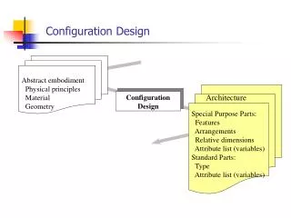
GENERAL ARRANGEMENT or CONFIGURATION DESIGN. Refers to the positioning of the major parts of the airplane Wing Fuselage Empennage Engines Landing gear in relation to each other. At this stage of the design game it is decided what the airplane will look like. CONFIGURATION DESIGN.

GENERAL ARRANGEMENT or CONFIGURATION DESIGN
E N D
Presentation Transcript
GENERAL ARRANGEMENTorCONFIGURATION DESIGN Refers to the positioning of the major parts of the airplane Wing Fuselage Empennage Engines Landing gear in relation to each other. At this stage of the design game it is decided what the airplane will look like.
CONFIGURATION DESIGN • Specific configurations are often inspired by a trend or line of evolution, which may have its origin somewhere in the past. • Marketing, emotional, and styling considerations also influence the configuration design. • A sound evaluation of practical solutions incorporated into existing successful designs should be the 1st step. • Excessively large departures from existing state of the art may lead to taking unwarranted commercial risks. • Competition forces manufacturers to explore new solutions, which is one of the reasons why competition has the long term effect of advancing technology.
CONFIGURATION DESIGN • Ideal configuration: the cg of WE, WF, WPL are all at the same longitudinal location. Why? • Limits cg travel. • Reduces Swet because there is less need for trim control power. • Impossible to achieve in practice; try to come as close to it as possible! • Fuel management cannot solve all your balance problems. • Don’t want to store fuel in the front of the fuselage because it is unsafe in a crash. • Electric motors used for fuel management are heavy because of the magnet’s low magnetic flux density. Some rare metals have 100 times higher mfd but they are very $$$.
CONFIGURATION DESIGN • Integration of major components (nacelle on wing, nacelle on fuselage, wing on fuselage, etc.) must be done so that interference D is min. • Any connecting, intersecting items should form angles as close to 900 as possible. • If this is not possible, extensive fairings will be needed to avoid D penalties. • At high M<1 it may be necessary to apply local area ruling to reduce Dwave. (B-747) • For M>1 airplanes, area ruling at several M is necessary. The ideal shape of the cross-sectional area distribution is the so-called Sears-Haack body of revolution.
CONFIGURATION DESIGN • Structural Synergism: major intersecting structural components should be arranged to avoid duplication of special heavy structure. • Example: High-wing transport w. fuselage mounted LG: attach LG to the same fuselage frames which are used to attach the wing. • Think: • Light • Simple • Accessibility • Maintainability • Cost • When a new configuration evolves, it is often the result of a large # of trade studies done by different teams trying to come up w. the most economical solution to some MR.