Download
1 / 28
280 likes | 539 Views
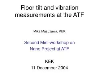
Floor Tilt and Vibration Measurements for the ATF2. Mika Masuzawa ,KEK IWAA06 29 September, 2006. Contents. Introduction ATF ATF2 Measurements: Co mparison between ATF and ATF2 Tilt measurements ATF ATF2 Vibration measurements Comparison Variation at ATF2 (day to day) Summary.

E N D
Floor Tilt and Vibration Measurements for the ATF2 Mika Masuzawa ,KEK IWAA06 29 September, 2006
Contents • Introduction • ATF • ATF2 • Measurements: Comparison between ATF and ATF2 • Tilt measurements • ATF • ATF2 • Vibration measurements • Comparison • Variation at ATF2 (day to day) • Summary
1. Introduction : ATF ATF (The Accelerator Test Facility) Built for R&D work for a future electron-positron linear collider. Produce, measure and control a very low emittance beam. Construction started in 1993 • by adding the damping ring to the pre-existing injection linac in the assembly building. • Reinforcement of the floor was needed. • A special foundation with more than 200 piles, 1 m in diameter and 14 m in length, was used. • Many expansion joints were introduced to prevent the floor from cracking due to thermal expansion and contraction. The expansion joints also play an important role in damping the floor motion and vibration.
1. Introduction: ATF Lowest among the same type accelerators Circumfrence 138m
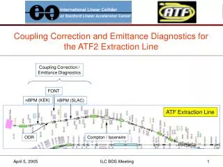
1. Introduction : ATF2 The ATF2 project will extend the existing ATF extraction line with an ILC-type final focus system. • Although the ATF2 beam energy is two orders of magnitude smaller than the ILC beam energy, many features of the ATF2 are common to the ILC final focus system. • The ATF2 optics design is identical to that for the ILC, and the natural chromaticity and the relative beam energy spread are similar. • The beam will be focused down to about 40 nm in the vertical direction at the IP, which is only a factor of ~5 larger than at the ILC. • Most of the tolerances, such as the tolerances on magnetic field, jitter vibration and power supply stability, are common between the ATF2 and the ILC. • The beam center has to be controlled to within a few nanometers at the IP.
1. Introduction : ATF2 With all the similarities between the ATF2 and the ILC , ATF2 will be a very good model for the ILC final focus system and a successful commissioning of the ATF2 project will assist in the design of the ILC. Do we need to re-do the floor outside of the ATF area? How large is the floor motion (tilt/vibrataion) there ?? Let’s measure them.
1. Introduction: ATF2 Assembly building ATF measurements (tilt & vibration) ATF2 measurements (tilt & vibration)
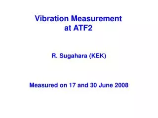
2a. Measurements Tilt measurements • Leica Nivel 20 digital tiltmeter Vibration measurements • Servo type velocity sensor VSE355G2 (Tokyo Sokushin Co. ,LTD.) For sensor resolution and huddle test results, →http://acfahep.kek.jp/subg/ir/nanoBPM/ • Servo acceleration sensor MG-102S (Tokkyo-kiki Co., LTD.) For sensor resolution and huddle test results, → R.Sugahara et.al., “Performance of an active vibration system for GLC”, IWAA2004.
2a. Measurements : Floor tilt at ATF At ATF beam line 10/25(Mon)-11/1(Mon) Access time to the beam area was limited. October 2004 S M T W Th F Sa X: perpendicular to the beam line (NS) Y: parallel to the beam line (EW) X Y Sensors on the floor
2a. Measurements : Floor tilt at ATF 50mrad Big spikes in both x/y at 10:40 am An earthquake occurred. No clear daily motion is seen.
The earthquake turned out to be one of the large aftershocks of the 2004 Mid-Niigata earthquake. The aftershock was reported as being magnitude6.1 (and an intensity level 6- on the 7-grade Japanese intensity scale at its origin in Niigata prefecture). The intensity level at the KEK area was 2~3. The 1st one (M 6.8) occurred on 24th. KEK
2a. Measurements : Floor tilt at ATF • No clear diurnal motion was seen. • No clear dependence on outside air temperature. • The floor tilt recovered smoothly after the earthquake.
2a. Measurements : Floor tilt at ATF2 Not as flat as ATF Outside air temp. dependence in x/y. X (north-south) drifts Atmospheric pressure?? 50mrad
2a. Measurements : Floor tilt at ATF2 • A clear day and night effect, about 10 mrad peak-to-peak, is seen in both x- and y- directions. • There seems to be a drift in the x-direction, which shows a weak correlation with the atmospheric pressure.
2b. Measurements : Floor vibration Chiller &pump Concrete shield Green floor ~2 m Yellow floor Floor paint removed For tilt measurements
2b. Measurements : Floor vibration amplitude comparison between ATF and ATF2 X V Y ATF2 (red) vibrates more than ATF(blue), especially in vertical. could be a problem…
2b. Measurements : Floor vibration comparison between ATF and ATF2 vertical ATF2 ATF Both measrured by acceleration sensors @14:00 April 1, 2004.
Amplitude of ground motion M.Masuzawa Presented at LCPAC at KEK,March 2006 by Andrei Seryi
2b. Measurements : Floor vibration comparison between ATF and ATF2 • We should try to damp the ATF2 floor vibration, to the level of the ATF area, by reinforcing the structure. • Especially since the amplitude of a girder is larger than that of a floor.see the next slide for an example. • We recommended that the ATF2 floor should be reinforced.
Vibration amplitude 10 The amplitude ratio of the vibration of the girder at the ATF beam line to the floor nearby. The present ATF girder vibrates more, by an order of magnitude than the floor!
What we will do … • The position of the final doublet quadrupoles (FD) must be stabilized to a few nm vertically and 50 nm horizontally. • Motion of FD with respect to the IP is most critical. • FD and IP will be installed on a common rigid support at ATF2 to reduce their relative motion. • IF FD were to be mounted independently from the IP (ILC), an active stabilization system will be needed. • High speed (> 10 Hz) and high resolution ( sub-nano level). • Such system might be tested at ATF2 (yesterday’s talk by Morita)
2b. Measurement : ATF2 floor vibration (~5 days)day to day variation December 2004 S M T W Th F Sa Weekend effect? Quieter Sunday Date
2b. Measurement : ATF2 floor vibration ,day to day variation “Anti-weekend” effectfor low-frequency ( f > 0.3Hz) floor vibration “Anti-weekend” effect is significant (several times larger) in X and Y. Not much effect in V. Why? Sunday Exceeds 1 mm
It was a very windy weekend Wave height and wave period at Port of Onahama Sunday
ATF2 floor (yellow) 2nd peak appears when the wave height was big. ATF2 floor (Green)
ATF2 floor vibration, wind speed and wave height 0.3Hz component follows wind speed?? 0.1Hz component follows wave height?? Floor vibrates on windy days. Unfortunately no data taken over this weekend at the current ATF beam line.
Summary • The diurnal effect in the floor tilt is a few times larger in the ATF2 beam extraction area than in the ATF beam line area. • The peak-to-peak daily tilt was measured to be 10 mrad in the ATF2 area when the outside air temperature varied by ~15 degrees. There was no such daily tilt in the ATF area. • An earthquake occurred during the measurement at the ATF area, but the floor tilt recovered smoothly.
Summary • The floor vibration is also larger in the ATF2, especially in the vertical direction. The vibration amplitude at 10 Hz is 50-60 nm in vertical, which is larger than the vertical beam spot size expected by the ATF2. • The ATF2 floor motion is significantly affected by strong wind and/or waves. This could be a result of the beam line being on the surface of the ground. • Reinforcement is needed in the ATF2 area. • Will be done as part of the ATF2 construction. • Stay tuned and see how well we can stabilize the beam at the ATF2. (with reinforced floor, good girder/mover, active stabilization system(?))