Download
1 / 11
110 likes | 210 Views
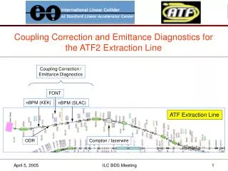
Coupling Correction and Emittance Diagnostics for the ATF2 Extraction Line. Coupling Correction / Emittance Diagnostics. FONT. nBPM (KEK). nBPM (SLAC). ATF Extraction Line. ODR. Compton / laserwire. Coupling Correction. ideally

E N D
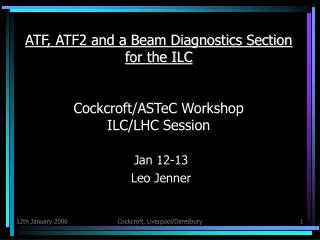
Coupling Correction and Emittance Diagnostics for the ATF2 Extraction Line Coupling Correction / Emittance Diagnostics FONT nBPM (KEK) nBPM (SLAC) ATF Extraction Line ODR Compton / laserwire ILC BDS Meeting
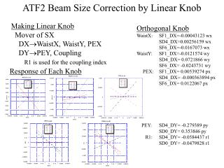
Coupling Correction • ideally • correction section with 4 independent skew quadrupoles, followed by • 2D (4 wire scanner) emittance measurement section • optics for orthogonal control of the 4 coupling phases • minimize εy once with each skew quadrupole • in present ATF extraction line • non-optimal optics in EXT straight section • wire scanners and skew quads interspersed • each wire scanner has x, y, and “u/v” (small angle, ~10°) wires • one attempt at full 4D beam matrix measurement and correction was inconclusive4 4 See http://atfweb.kek.jp/atf/Reports/ATF-99-01.pdf ILC BDS Meeting
“Ideal” skew correction / ε diagnostic section SQ SQ SQ SQ WS WS WS WS – x – y 90° 90° 180° 90° 90° 90° 45° 45° 45° 45° 45° 45° See http://www.slac.stanford.edu/cgi-wrap/getdoc/slac-pub-8581.pdf ILC BDS Meeting
WS WS WS WS WS SQ SQ SQ SQ – x – y L = 11.43 m 5° 8° 13° 20° 30° 36° ILC BDS Meeting
SQ SQ SQ SQ 1.2 1.2 1.7 1.7 1.1 1.3 1.1 0.9 0.9 0.9 0.7 1.3 1.1 WS WS WS WS WS – x – y 32° 48° 51° 21° 32° 58° 58° 32° L = 20.58 m ΔL ≈ 10 m σWS > 5 μ ILC BDS Meeting
SQ SQ SQ SQ 0.8 0.7 1.7 1.7 0.6 0.8 0.6 0.5 0.5 0.5 0.3 0.8 0.6 WS WS WS WS WS – x – y 31° 40° 41° 13° 32° 58° 58° 32° L = 15.80 m ΔL ≈ 5 m ILC BDS Meeting
A ‘Drift’ e-Diagnostic Section from Paul Emma … b s L w1 w2 w3 3 wire scanners (or profile monitors) ILC BDS Meeting
– x – y σmin = 3 μ ILC BDS Meeting
Emittance Growth in ILC Upstream Polarimeter/Spectrometer Chicanes 1.4 m ILC BDS Meeting
γε/γε0 = 9.610-6η5 ILC BDS Meeting